Controller wiring

Thanks again for the reply. I will start the hunt and get back to you.

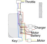
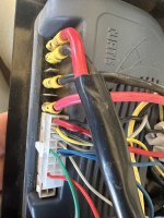
Yes all the previous tests were conducted on the wire loom in the above photo without the throttle connected.

Something I totally forgot to mention, as too focused on the controller and loom, the blue and red wires sitting to the bottom in the above photo goes to a little LED head light. Unsure if this would be adding to the issue somehow?

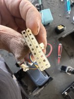
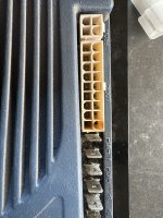
Also when my mother in-law first asked me to look at this I found the below issue with the main controller plug. The positive from the charge port had seen some serious heat and the individual socket had snapped off the plug. This was along with the busted spring perch in the throttle.
I replaced the plug and repined it then pulled throttle apart and “rebuilt” the spring perch. I put it back together and it all worked until the spring perch snapped again and busted the wires off the hall sensor. Later found out the reason the throttle spring snapped a second time was from my mother in law twisting the throttle forward to go forward 🤦🏻‍♂️.

As it is taking charge and was working after the plug change I didn’t think this would add to the throttle issue at all but thought I better mention it just in case.
 

Attachments

  • IMG_5601.jpeg
    IMG_5601.jpeg
    1.5 MB · Views: 6
  • IMG_5602.jpeg
    IMG_5602.jpeg
    2 MB · Views: 6
All information is welcome.

The light wiring could certainly come into play, as you’re now looking for a break or open in the ground. As well as it being shorted to a positive battery source. So on your resistance checks, expand to include close positive power wiring to identify what it’s shorted to…
 
With the multimeter set to ohms and on the 200 setting I get 0.04 ohms from the bare wires to the first connector. Tested one wire at a time.

With the first connector back in and checking from the cut wire loom back I get the below at the next plug. The negative is on the cut wires one at a time.

Blue changes to black 1.8
Green changes to white 2.3
Red changes to yellow 0.5
Yellow changes to blue 0.6

With the next plug reconnected and checking at the next plug which connects directly to the controller. The negative is still on the cut loom one at a time.

Blue which remains black to the controller 1.6
Green which remains white to the controller 1.0
Red which changes back to red after the last plug is 1 . I disconnected the plug and tested at both ends of the red wire here and get the same result. Assume there is an issue there.
Yellow which remains blue to the controller 0.6

At the main controller loom back to the next plugs, negative on the main controller plug one at a time and the positive at the other plug.
The key switch plug blue 0.3 and yellow 0.2. I didn’t test anything at the actual key as hard moulded plastic case which I can’t see how to get off without breaking it.
The plug that goes to the motor Green 0.3 and red 0.2. I didn’t test at the motor as don’t want to remove the weather protection but will if required, please advise.
The red wire in the power plug that leads to the charger 0.3
The second plug that leads to the charger Black 0.3 and Grey 0.2
From the charge port to the plugs, black, grey and red all read 0.3

I haven’t checked the main red and black leads to the motors as don’t really want to pull all the weather protection off them to check. If need be I will, please advise if it is required.
 
Last edited:
I pulled the red pin that wasn’t getting a result and the wire wasn’t in the pin correctly. Looks like I may have pulled it out when disconnecting the main plug.
I crimped the pin properly and checked again and getting 0.3 from the cut wire to the red of the main controller plug.
 
Last edited:
I have retested as per you first instructions after finding the issue with the red wire at the controller and fixing it.
With the 4 loom wires not connected to the throttle. When I turn the key on, with the red test probe on yellow loom wire and the black probe on blue loom wire, I get a split second spike of volts, each time I turn the key on it is different ranging from 19v to 1.4v and heaps in between then goes straight back to zero. When I key off I get a negative volt for a split second similar to the above, each time different than the last.
With black probe still on the blue wire I have no voltages from the other 2 wires.

Probably worth mentioning previously if I touched the bare blue and green wires the motor would run. Now it sparks after fixing the red main controller wire. Accidentally touched them momentarily and sparked so covered them all individually with tape to ensure they don’t touch again while moving forward.
 
Last edited:
Floyd it is a Curtis controller but can’t see a model number anywhere but looks very similar to what you have posted. Thanks
 

Attachments

  • IMG_6665.jpeg
    IMG_6665.jpeg
    1.3 MB · Views: 5
Last edited:
The 1228 controller looks like it is a match. It is used for mobility scooters among other applications. Based on 4 pin programing port, 18 pin connector, M1 2 spade connecters ,M2 2spade connecters , Battery 2 spade connecters. The model no may be on one of the ends or he paper labels may just be missing.
later floyd
 
Cheers! to floydr for identifying and providing a manual for the OP's controller. Such a great advantage.

syco26,
Thank you for the detailed and methodical testing and sorting out of the harness (AKA- loom) wire colors.
The poor wiring color changes from possible positive, negative, and signal wiring seems a bit egregious.
Did you check on the back mounting side of the controller for the sticker?

Good catch and repair of that bad reverse signal wire pin. (y)

Probably worth mentioning previously if I touched the bare blue and green wires the motor would run.
As the Blue wire now has unwanted positive voltage on it, if it provided ~1 to 5 vdc (or greater if the controller can take it- unknown but NOT recommended to try!), to pin 4 WHITE wire (GREEN at upper loom.)... the motor should run.

On the resistance checks... a measurement of 3 ohms or less would not demand attention in this instance and would be considered a good wiring circuit.

To continue the task of correcting the bad ground to the throttle...

As always, if you are unsure at all of my descriptions or meaning. Or you're not getting the expected results... Please ask me to verify or explain further BEFORE you wire or test or move on to a next step.

For reference... or see the manual. Note: Pay little attention to the throttle wiring here. Recommend you copy, color in the wires with added connection locations.

E2y9BZD.jpg


With everything back together. Batteries disconnected.
From bare BLUE wire top of the throttle loom, to back probing the Pin 2 BLACK wire on the controller's main connector(this is the throttle's ground termination spot... isn't it?). Is this circuit good? I.E. Passes resistance test.
If so, remove the 18-pin connector from controller. And take a resistance reading from PIN 2 on the controller, to the BLACK wire disconnected connection of the battery cable connector. (controller side- no voltage!) If you find this open, the internal pathway to ground would be bad. Time to try another grounding point to see if the controller is still viable.

Remove the BLACK wire from the main connector at the controller. (pin 2)
After removing the BLACK throttle ground wire, you should test the pin 2 for voltage (batteries hooked up, key ON)
I would expect a voltage reading... Bad.
Then test throttle ground wire to make sure voltage is gone from it... good.
Run a jumper wire from the disconnected BLACK throttle ground wire (leave the connector on it) to a negative post of the most convenient battery.

Start from the beginning testing instructions, testing in steps and see if the desired results are there.

There may be other viable grounding pins in that main connector, if it's working.
 
Last edited:
Hello TC.

See attached sticker on the back of the controller. Thanks Floyd, you were correct with the model number.
I have also done a pretty crappy wiring diagram. Please note the pink is actually white, had to use a colour due to the white background.

With the batteries disconnected and from the bare blue of the throttle loom to probing number two pin I get 0.07 ohms. Yes believe the number 2 is the throttle negative.

With the 18-pin connector removed from pin 2 to the negative of the battery lead, disconnected from the battery, I get 1 . Going from the battery negative lead to any negative on the controller gives me the same result. Tried pins 2, pin 1, M2 ground and B- (where the battery negative loom goes).

I haven’t moved to the next part because I want to confirm I am reading it correctly. You want me to de-pin number 2 on the 18-pin connector. The negative probe to pin 2, where should I stick the positive probe to check for voltage? Straight to the battery positive?

You then ask to test the throttle ground wire. Is that with it still out of the 18-pin and just probe either end? The end of the wire that goes to pin 2 and the cut wire at the throttle loom? When I run a jumper wire from the disconnected black throttle ground wire to a negative post of the most convenient battery where do you want me to probe?

Sorry for the dumb questions. May be easy to decipher for others but I am not 100% sure and don’t want to stuff it any more than I have.

Thanks to everyone for the help so far.
 

Attachments

  • IMG_6676.jpeg
    IMG_6676.jpeg
    1.8 MB · Views: 9
  • IMG_6675.jpeg
    IMG_6675.jpeg
    94.8 KB · Views: 7
Last edited:
With the 18-pin connector removed from pin 2 to the negative of the battery lead, disconnected from the battery, I get 1 . Going from the battery negative lead to any negative on the controller gives me the same result. Tried pins 2, pin 1, M2 ground and B- (where the battery negative loom goes).
Try pin 13.


I haven’t moved to the next part because I want to confirm I am reading it correctly. You want me to de-pin number 2 on the 18-pin connector. The negative probe to pin 2, where should I stick the positive probe to check for voltage? Straight to the battery positive?
Yes, de-pin BLACK wire leaving connector on it.

”After removing the BLACK throttle ground wire, you should test the pin 2 for voltage (batteries hooked up, key ON)
I would expect a voltage reading... Bad.”

Checking for voltage (unwanted): put the RED meter probe on pin 2 with the BLACK meter probe on the battery’s negative pole. Change to voltage reading… Power up system.

Do the same check for voltage at the disconnected end of the ground circuit. Looking for no voltage present.
RED probe to BLACK wire end, BLACK probe to battery negative pole
 
Sorry, must have stuffed up on the last test. I tested on one of the battery plug ends but was on the negative of one battery plug that goes to the positive of the other battery plug. Retested on the battery plug negative that goes to the controller. With the negative lead of the multimeter to the battery lead, disconnected from the battery, and the positive to the controller pins I get 0.03 on pin 1, 0.02 on pin 2 and on pin 13 I had to change the ohm range from 200 to 2k and get .520. Checked all the other pins and get 1 .

With the number 2 negative pulled from the 18-pin connector, the 18-pin plugged back into the controller, the multimeter positive lead jammed into the 18-pin connector touching the number 2 pin and the multimeter negative lead on the battery and the key off I get a split second of -01.1 volts then if I remove the multimeter negative lead from the battery I get a split second of 3.2. After the split second of a reading it goes to 0.00 volts. Dong this numerous times renders different readings below the above numbers for a split second then back to zero. If I leave the negative on the battery and turn the key on it stays at zero. Doing the same test with the 18-pin disconnected from the controller and red straight onto pin 2 gives the same results.

For your next step “Do the same check for voltage at the disconnected end of the ground circuit. Looking for no voltage present. RED probe to BLACK wire end, BLACK probe to battery negative pole” do you want the ground back into the 18-pin and connected to the controller?
 
Sorry TC, not following. “The disconnected ground circuit” are you talking about the black lead I pulled from the 18-pin plug number 2?

If so I have a bare wire one end with the exposed terminal on the other end and the couple connected plugs in between the two ends. Red probe to the exposed throttle end (which would be the blue wire), the black probe on the battery negative. What do I connect to the black wire terminal end to complete the circuit or just leave it hanging?

I have checked and get I get a similar result as above (this is with nothing attached to the black terminal end from pin 2 while it is just hanging), split second of volts jump then zero when touching the black to the battery negative then 0.00 constant. Is the same when removing the negative terminal. This is the same with the key on or off while the 18-pin is disconnected and the same with the 18-pin back in, I assume testing for a short in the loom somewhere?
 
Last edited:
Exactly. It seems that the mysterious 24vdc positive power that was in the throttle’s ground circuit has disappeared??
Now no voltage on the loom circuit, as well as pin 2 that completes the circuit to the negative of the battery.
And you have continuity from the top to the bottom of the loom of the ground circuit.
I’m at a loss…

Reconnect everything and go back to testing voltage at the raw 4 wires a the top of the throttle loom (RED meter probe at top with the BLACK on battery negative post. (Or terminal 5)

Looking over your data points looking for a flaw in my logic. :-/
 
Last edited:
I may need to redo a couple of those tests above. I had the multimeter on V~. I just connected everything and wasn’t getting a result at the throttle end of the cables. Changed the meter to V with the dash line and solid line above and get 24v on the yellow cable, 0.00 on the other three when the positive is on the wires and the negative on the negative of the battery.
 
I just reconnected the wires the the throttle and the LED light lite up, hasn’t done this for a while. Tried the mag from the twist throttle on the hall sensor and 🥳🥳🥳 the back wheels started turning. Move the mag strip across the hall sensor and the wheels turn faster on way and stop when I go the other way.

I’ll pull the internals out of the 6 wire body and put the internals from the 4 wire into that body and assemble and see how it goes. Looks like we are on a winner though.

Thank you all so much for the help.
 
I have pulled the body off the 6 wire controller. Put the four wire internals in it. Put it all back together and tried it and all good. Forward as it used to with progressive throttle. Reverse switch works and goes backwards with the throttle.

Thanks all for the help. It is greatly appreciated. Think it end up being the combination of the stuffed hall sensor and the throttle input in pin 17 that was at fault, well at least I think that is what it was.

Learnt a heap as well, so again thank you all for the help.
 
From the depths of despair to the thrill of victory in less than 2 hours... took me a day to recover. :p
My congratulations on your persistence and success. JOB WELL DONE!


Best regards,
T.C.
 
Back
Top