Controller wiring

syco26

10 mW
Joined
Dec 1, 2023
Messages
23
Location
South Australia
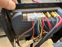
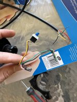
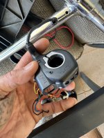
I have just purchased a replacement throttle, pt# 29DX. It is branded Wuxing. The unit it is replacing is the same brand and part number. The issue is the new controller is a 6 wire and the old is a 4 wire.

I have tried wiring the new unit but not having any luck at all.

Anyone able to point me in the right direction to get this wired up and working?

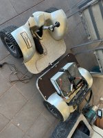
The first photo is the old controller next to the new controller.
The second photo is the old controller wiring pulled out for a better view.
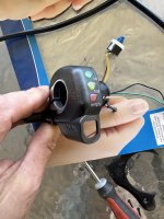
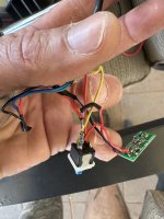
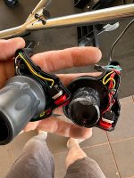
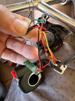
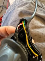
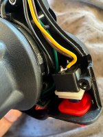
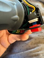
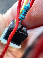
The next three are inside the new controller.
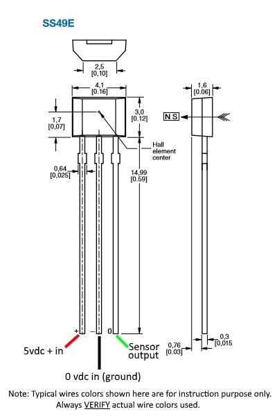
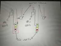
The 6th is a crude drawing of the wiring. Note the grey wire is the white.
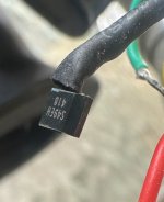
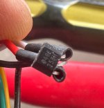
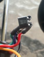
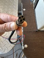
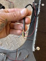
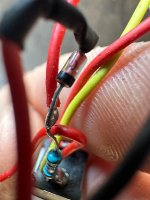
And the last couple are the resister and diode (think that’s what they are) in the old 4 wire controller.
 

Attachments

  • IMG_2023-12-1-190655.jpeg
    IMG_2023-12-1-190655.jpeg
    191.2 KB · Views: 39
  • IMG_2023-12-1-190754.jpeg
    IMG_2023-12-1-190754.jpeg
    211.3 KB · Views: 38
  • IMG_2023-12-1-190859.jpeg
    IMG_2023-12-1-190859.jpeg
    172.3 KB · Views: 31
  • IMG_2023-12-1-190933.jpeg
    IMG_2023-12-1-190933.jpeg
    189.6 KB · Views: 24
  • IMG_2023-12-1-190953.jpeg
    IMG_2023-12-1-190953.jpeg
    172.4 KB · Views: 36
  • IMG_2023-12-1-191014.jpeg
    IMG_2023-12-1-191014.jpeg
    118.6 KB · Views: 37
  • IMG_2023-12-1-191115.jpeg
    IMG_2023-12-1-191115.jpeg
    142.1 KB · Views: 36
  • IMG_2023-12-1-191143.jpeg
    IMG_2023-12-1-191143.jpeg
    140.4 KB · Views: 31
Let's look your old throttle's wiring diagram
Red- is battery power.
Black - ground for both the LED panal and the Hall device
Green - the Hall device output
Blue -for the on/off switch sending battery power back to the controller to turn it on. It also powers up the LED board.

Where is the 5V power used to power hall effect device? They are using the resistor with a zener diode to drop the battery voltage down to 5 V to power the hall device, This sure is a cheap design.

Your six wire throttle uses the normal three wires to power the throttle. I think red is 5 volts, black is ground, and white is the output. Then a different red is battery power, and yellow/green are tied together. You need 5V to run the Hall device. You could bring it out from the controller to the handlebars, or manufacture it with a resistor/diode like the first one,.

The big question is if you accidentally blew up the throttle by putting battery power on the red line that was meant for 5V.
 
Thanks for the reply.

Just to confirm is Yellow the ground? You said black but there is no black wire going in but the black is soldered to the switch pole with the yellow.

Also you said the other red, assuming you mean brown, is battery power. Do I connect that with the yellow and green or just yellow and green together?

So will the below work, first colours mentioned being the old wiring and second being the new? Providing I haven’t stuffed the new controller already.

Red to brown, yellow and green, also run the diode to the new red.
Yellow to black
Green to white
Where does the blue go?

Sorry for the very uneducated questions.
 
Or should I just bite the bullet and purchase this? Won’t arrive until next year and was hoping to get this working before then. It is a 4 wire with the same colours so hopefully will work.
 
I only looked at your schematic, and didn't see that on the old throttle, ground is both black and blue. Yellow is NOT ground. You have it right on your schematic, but the schematic is drawn wrong for the diode and the resistor. The diode comesoff the end of the resistor, and the red wire at the junction goes to the LED card?

Summary:
Old throttle.
Green - throttle output
Blue - ground
Red -Battery power
Yellow - switches to battery power when throttle is on,

New Throttle
White - throttle output
Red - +5V power
Black - ground for IC and also LED panel
Brown - Battery power
Yellow = Switches to battery power with switch
Green - Power for the LED panel. Tie this to Yellow,.

So I believe this is how I would do it, but proceed at your own risk.
New Green to new yellow.
New white connects to old green.
New black to old black,
New Brown to old red.
New Red needs +5V, and your bike harness doesn't have it,

That still leaves you w/o +5V power to run the Hall chip, If the old throttle still puts outs out 5V at the end of the diode. you could move that to the new one.. I think it's better, unless you're good at electronics, to buy that 4 wire throttle.
 
Thanks for the reply. Will give it a go.

Just to confirm.

New Green to new yellow. Should this connect to the old yellow as well?
New white connects to old green.
New black to old black (assuming old blue?)
New Brown to old red.
New Red needs +5V (use diode to old red?)
 
Last edited:
That didn’t work either. Potentially fried the new controller when I connected the straight power to it?

Have bit the bullet and purchased the slightly different 4 wire controller. Hopefully that will work.

Thanks for the help.
 
The old blue is ground, The new black goes to it,
And the new yellow/green also connects to old yellow. That;s battery power, which should never go to ground,

But it can't work without power to the throttle. And if battery power had reached either the red or the white leads, it's blown up,
 
The new controller arrived. I did stuff up though as didn’t notice at the time of purchase that the new controller didn’t have a button for reverse.

It is a 4 wire controller with Red, Yellow, Blue and Green the same as the current harness.

Connected like for like colour and turned it on and nothing. Nothing happens when I turn the throttle.

If I turn it off at the key and disconnect them all then key back on and connect them one by one as soon as the green is to the green and either blue or yellow go to the same colours the wheels start turning with no turn of the throttle.

If I connect the red, then green same results, as soon as the yellow is on yellow or blue is on blue the wheels start turning with no throttle input. With all connected and wheels turning if I turn the key off then on again I get nothing.

On the main harness if I touch the green and yellow or green and blue the wheels turn. Assuming green is positive. Red to any of them does nothing.

Not sure what is wrong with it besides my lack of electrician skills. Just want it going for my mother in law.
 
man doc has put some effort into understanding this, I haven't looked too closely, but I used to use zener diodes to drop voltage by 12v usually so that I could use 36v throttle leds to work with 24v throttle leds, was convenient way to do it, also of course can do same for 48v leds battery monitor to work on 24v or 36v throttle. Very simple and convenient.
 
At this point, I can only grope around in the dark with my recommendations. It was cool that you opened up the old throttle to look at the layout, but it doesn’t seem to have added much clarity to this troubleshooting — at least for me, anyway.

It’s easiest to replace like with like - a four wire throttle for a for wire throttle.

My first guess is that on the new throttle:
Red: +5V
Green: ground
Yellow: hall signal
Blue: battery positive voltage for the little LED display

I’d start there, but know that you can potentially extinguish another throttle with the wrong wiring.

Also - the new throttle is labeled as a 24v scooter throttle. Are you using it with a 24V scooter or ebike?
 

Attachments

  • 5326FCEE-2887-4961-85D3-9600DAD96BDF.png
    5326FCEE-2887-4961-85D3-9600DAD96BDF.png
    529.9 KB · Views: 6
I do not follow. You're mixing terms, by originally calling the throttle a controller in your title. You had a 4 wire and a six wire throttle. You said you were going to bite the bullet and buy this second throttle

Now you report a new controller has arrived. I thought you meant the above throttle showed up. It doesn't work.

But then I saw the comment about not having a reverse switch, So this is a new controller, with a 4 wire throttle interface, plus the old throttle?

There are a lot of different variables. Why did you replace the original throttle? Was it not working? Maybe it won't work with the new controller for the same reason. Maybe the new controller isn't wired correctly.


.
 
As the descriptions for the various throttle pictures specify controllers... I believe the OP is switching back and forth between "controller" and "throttle" meaning the same thing, a THROTTLE.

What has been fascinating me is how you can get a voltage display, hall sensor throttle, and reverse operation out of 4 input wires. :unsure:

I think that voltage measurements, using the controller's BLUE wire as ground, at all the old throttle wiring connections would be most helpful. Especially to both sides of the diode & resistor. (The more data points the better. ;) Correct and then add voltage reading points to your wiring diagram may be the easiest way to avoid confusion)

Regards,
T.C.
 
Thank you all for the replies. Sorry for any confusion with terminology. I am by no means an electrician, tinker in my garage and enjoy trying to fix busted things, usually. Thought cause I have rewired things in my car that I could handle changing a throttle controller, I was obviously very wrong.

The original throttle controllers spring perch snapped. I pulled it apart and tried to mend the broken bits, it held for about a little while but broke again. When I pulled it apart the second time I noticed that one of the wires on the hall switch/sensor was snapped off, not sure if it happened when the spring let go or if I stuffed it pulling it apart but is now not working.

I googled the part number and brand, Wuxing 29DX, and ordered a replacement. The first that arrived was a 6 wire although the original, with the same brand and part number, was a 4 wire.

I purchased the second throttle controller in the link I shared as was the only I could find that was similar and a 4 wire. Didn’t notice it had no reverse button like the original only after it arrived.

Forgot to mention when I first connected the 4 wire controller to the 4 wire loom, same colour wires connected, I would get a blink of light from the LED’s on the display when I turned the key on. This happened a few times. Now I get nothing. Most likely fried it already from my absolutely lack of electrical knowledge.

I have spent ages googling the 29DX trying to find a 4 wire replacement but all seem to be 6 wires.


Thank you all for the help but think I have to admit that I really have no idea what I am doing and need to take it to someone for help.
 
Last edited:
Maybe a long shot but do you think I could cut one of the hall sensors from one of the other throttle controllers and use it to replace the original busted one? Then I will put the components into the new 6 wire body that has an intact spring perch.
The first photo is the original hall sensor (think that is what it is called), as you can see the green wire has come out of it and the red has snapped off at the post not leaving enough to solder to. The second is the 6 wire. The last is the new 4 wire, this one appears the closest as same colour wires going in it. However all have different numbers on them.
 

Attachments

  • IMG_6610.jpeg
    IMG_6610.jpeg
    1.2 MB · Views: 7
  • IMG_6611.jpeg
    IMG_6611.jpeg
    1.3 MB · Views: 7
  • IMG_6612.jpeg
    IMG_6612.jpeg
    1.3 MB · Views: 7
Gave that a try but no good either. Took the third hall sensor and soldered it into the old unit but no good. Connect all the wires then key on and nothing happens.
If I disconnect the wires then key on and add wires one at a time as soon as the green is to green and blue is to blue the wheels turn. Connect all and they continue to turn. Key off then on again and nothing.
 
So I tried to test the function of the hall sensors.
On the 6 wire that is still complete if I use the red as a positive and the black as a negative onto a 4v pack I get between .8v and 3.6v when rotating the throttle controller.

On the old unit with the hall sensor out of the new unit I get no change. Sits at a constant 1.1v. That is red as positive, blue as negative and green as the signal wire. Think that hall is stuffed.

At the wires on the cart I get -22.4 with the positive lead on the green and negative lead on the blue.
I get -23.7 with the positive lead on the green and negative lead on the yellow.
With the positive lead on the green and negative lead on the red I get -00.0 but if I touch the lead I get -00.2.

With the positive lead to the blue and negative to the yellow I get -00.2.
With the positive lead to the blue and negative to the green I get 22.6.
With the positive lead to the blue and negative to the red I get 00.1 but if I touch the red only it jumps to 6.8.

Not sure if any of that will help.

Was thinking about cutting the hall sensor from the 6 wire and giving that a go but as it still appears to be working but don’t really want to stuff it if I can somehow get it to work.

I have just tried a toggle switch instead of a throttle controller which works but get all or nothing which I can see will end in tears.
 
Last edited:
You can help with more pictures. Suggestions.

1. A picture of the original throttle-controller connection. That throttle internal wires were red. (power) green (hall signal) , blue (ground) and yellow (controller start). I imagine they would be the same at the plug, but want to see the plug.

2. A picture of the new throttle.

3. And a description of what you're trying to move. Kick scooter, Mobility trike?
 
Hey Doc. Pictures of the first and second controller in my original post. No point in seeing photos of the third controller as I cut the Hall effect sensor out of it to try on the first controller and is now in the bin. It was basically three wires to the hall, the negative went to the LED display along with the 4th wire, yellow from memory.

Have attached more photos. First two are the original throttle controller and the components inside. It is a Wuxing 29DX with 4 wires coming out of it. This now has the other hall sensor in it that I cut from the third controller and soldered in at the wires.
The next two are the second controller and components inside. It is a Wuxing 29DX with 6 wires coming out of it. I purchased it due to the name and part number being the same and didn’t realise it was a six wire.
The next two photos are the wires I cut from the original controller, at the handle bar attachment point and the plug that connects under the unit. I am splicing at the cut joint currently and not trying to rewire the plug.
The last three are the unit itself, the dual batteries and the control box that feeds off to the motors underneath.

It is my mother in laws electric golf cart. The company that sold that brand here in Aus is no longer trading so can’t reach out to them.
 

Attachments

  • IMG_6630.jpeg
    IMG_6630.jpeg
    2.5 MB · Views: 6
  • IMG_6629.jpeg
    IMG_6629.jpeg
    2.7 MB · Views: 9
  • IMG_6628.jpeg
    IMG_6628.jpeg
    2.7 MB · Views: 12
  • IMG_6627.jpeg
    IMG_6627.jpeg
    1.4 MB · Views: 8
  • IMG_6626.jpeg
    IMG_6626.jpeg
    1.5 MB · Views: 45
  • IMG_6625.jpeg
    IMG_6625.jpeg
    1.8 MB · Views: 5
  • IMG_6624.jpeg
    IMG_6624.jpeg
    1.6 MB · Views: 5
  • IMG_6623.jpeg
    IMG_6623.jpeg
    1.1 MB · Views: 5
  • IMG_6622.jpeg
    IMG_6622.jpeg
    1.6 MB · Views: 5
Hi syco26,

Please read thru this and my next post in entirety before proceeding... Thanks.

The first photo is the original hall sensor (think that is what it is called)
You are correct, it is a hall sensor. More specifically a 49E model.

Glad to see you back in it replacing the original throttle's broken hall sensor after disclosing that the original problem was a purely mechanical one.
Even better, breaking out the multi meter and verifying if the other hall sensors are still working properly before installation. Well done. Those hall sensor voltage reading with the bench power source are right on the money. These output voltages are what you need to see when all is well.
I don't know what happened between those readings, and the couple next sets... seems that the polarity got switched...?
Double check that your meter's BLACK probe is in the common or ground jack. This is your negative test lead.
With the RED probe going to the voltage jack. This will be probing for positive voltages.
Finally, the meter scale selection to the next highest voltage above 24 volts D.C. Or auto-ranging DCV. if available.

A few important points up front...
When I mention throttle, it is the new parts with the hall sensors that you are twisting to get the cart to go.
When I mention controller, it is the grey OEM part at the back of the batteries with all the wiring coming out of it.
Stop changing wires around and jumping wires with guesses! STOP IT. :eek:
So far it sounds like you've been lucky enough to not damage the controller, but I don't think the hall sensors are faring too well.
Hall sensors drop dead voltage if exposed to is 8VDC. Do not let any 24VDC voltage come or touch any hall sensor legs.
Keep all exposed electrical wires from contacting anything else. Isolate and/or tie off if not needed for testing.


I have just tried a toggle switch instead of a throttle controller which works but get all or nothing which I can see will end in tears.
Agreed. :)

Thank you for the new pictures. Always nice to see what one is working on, and they can also give new clues to solving the problem.


I would like to propose a different identification of the wires and their functions...

From the controller, bare wires cut off from the round connector...

YELLOW: I do believe that this is the battery positive feed to the throttle assembly.
GREEN: This is the hall sensor's output path or signal wire back to the controller.
BLUE: This goes to battery negative or ground wire.
RED: This is a bit different as I think that this is the battery positive return line to the controller, which calls for reverse.

Let's start by verifying my thoughts.
First, with the 4 loom wires NOT connected to the throttle. Verify that you have 24 volts positive at the yellow wire just when you turn the key switch "ON", the one between the batteries. (RED test probe on YELLOW loom wire- BLACK probe on BLUE loom wire. If you have positive voltage there at the correct time we will continue. Then with BLACK probe staying on the BLUE wire, you should have no voltages from the other 2.

Need to go to breakfast, will be back soon to continue.

Regards,
T.C.
 
Last edited:
Sorry for any confusion with terminology. I am by no means an electrician, tinker in my garage and enjoy trying to fix busted things, usually. Thought cause I have rewired things in my car that I could handle changing a throttle controller, I was obviously very wrong.
Hey Doc. Pictures of the first and second controller in my original post. No point in seeing photos of the third controller as I cut the Hall effect sensor out of it to try on the first controller and is now in the bin. It was basically three wires to the hall, the negative went to the LED display along with the 4th wire, yellow from memory.
Maybe switch to the correct terminology going forward would help. Also, performing some measurements before randomly connecting wires could help troubleshoot the current problem without introducing new ones. One wrong connection can fry the throttle or controller, making troubleshooting a lot harder.
 
Thanks. This is a good start
mobility_ee.jpeg

Now we need to know how the wires from this connector trace to the above harness. The new throttle should work, but not if you somehow transposed the wires when you made the connection, ` Or the golf cart used different colors after the 4 pin connector, Seeing what you did there should explain what happened.

commer.jpeg

With your multimeter, everyone will relax after you verify which one of those four wires is 24 volts, but first you have to find ground.
 
Continuing on from my previous post...

You can verify for me that "YES" the RED button on your original throttle allowed the cart to run in reverse.

Make sure the power is off between wiring changes and turned on just before testing...

A quick check of your hall sensor wiring, it looks good but please verify...

gXMVqVm.jpg

As you look at the print facing you on the beveled side, the flat side to the back, correct connections are shown.

If the previous voltage checks proved successful, we move on...
As you might be realizing by now is that the original throttle's resistor with zener diode circuit must be used and operating correctly.
This provides the 5vdc voltage source used for the hall sensor's operation.
From the pictures it looks like you have everything in the original positions with the hall sensor replaced.

Leave the throttle open at this time to take some voltage readings.
At this time connect just the YELLOW loom wire to the original throttle wiring YELLOW wire. (Which terminates at one side of the switch.)
And the BLUE loom wire to the original throttle's BLUE wire. (Which terminates at the middle leg of the hall sensor, tying together with a BLACK wire that continues on and terminates at the negative power pad of the LED board.

With the remaining two wires, RED and GREEN loom wires still disconnected and isolated.
Power up the system. The LED lights should illuminate at this time. If not make tests below.

Verify full battery voltage positive present the way you did earlier with the meter. You can also check with the meter's Black probe on the negative LED termination connection (where the BLACK and RED wires meet together), and the meter's RED probe on the LED's + (positive) pad termination where the single RED wire is soldered to.

As always, if you are unsure at all of my descriptions or meaning. Or you're not getting the expected results... Please ask me to verify or explain further BEFORE you wire or test or move on to a next step.

If so far so good, now comes a critical test...
Still, with just the 2 wires connected. (YELLOW and BLUE) Leaving your meter's BLACK test probe on the BLUE ground wire. (Or any throttle internal BLACK wire access.)
Touch the RED probe wire to the junction of where the RED hall sensor wire ties in located between the zener diode and the resistor.
I would expect to see a voltage of between 4.5 and 5.5VDC and will refer to this voltage in the future as 5vdc. If not... stop here. If so please continue.

At this time I can see hooking up the GREEN loom wire to the throttle's GREEN wire. Be prepared for motor activation! Power up.
With the meter's BLACK probe still on the BLUE wire, test the output of the hall sensor. It should give you the near the same readings as your bench testing showed earlier. With the motor spinning up from a full stop to maximum speed as per the throttle's position.

Hopefully the only thing left is to connect the looms RED wire which goes to the old throttle's RED wire that terminates on the other side of the switch opposite the YELLOW wire. (NOT the RED that goes to the hall sensor.) At this time reverse should be operational.

Good luck, will be checking in for results,
T.C.
 
Sorry for the late reply, was out of town yesterday.

TC following your instructions, negative to the blue and positive to the yellow. With the key off I get 0.00v and when I key on I get 00.2v.

With the negative still on the blue I get 0.00v on the red with the key off then when I switch the key on I get a split second of -0.04 then drops to -0.00.

When I connect the positive on the green with the negative still on the blue I get 0.00 with the key off and -22.5v when the key is on.

Checking with the negative on the negative on the battery and the positive to the other cables one at a time I get 0.00v on all when the key is off then the below once key is on.

Yellow 24.3v
Blue 23.1v
Red 0.05 when the key is first on then drops to 0.01v
Green 0.00v

I haven’t progressed to the next lot of tests as not getting the results you expected from the above test and will await another reply.

For your other questions.

YES the red button on the throttle was the reverse button.

Yes the hall sensor is wired as per the picture, red, blue in the middle and green to the right when the writing is facing up. This is how the original hall was connected also. However the red doesn’t go directly to the hall. It goes to one side of the switch after the diode and before the resistor. The same pole as the yellow. The other pole of the switch is connected straight to the red of the loom. I have attached another photo that shows it all a little better. This is how the original was wired up, all I changed was adding the replacement hall.

As I believe that the hall sensor I soldered into the original throttle is already dead (from me connecting the wires prior to any confirmation of voltage) and the fact the first steps haven’t given the desired results I haven’t done any other test as mentioned yet.

I have ordered a couple new Hall effect sensors two days ago as believe the unit I installed into the original throttle is shagged. Didn’t want to cut the hall from the 6 wire throttle incase we can get it to work somehow.


E-Hp, sorry about the lack of correct terminology. By no means a sparkie and honestly had no idea what half this was called before playing with it. I honestly thought all these wires would have been low voltage signal wires and didn’t think there would be any “high” voltage running to the throttle when I started this. Learnt by my mistake there and will ensure anytime I do anything like this in the future I will use a volt meter before just trying different wires. Glad these parts were relatively cheap to replace. Could have been costly if playing with something else.


Doc on the controller the first red (going from left to right) goes to the throttle wire loom.
The next red and green go to the motor.
The pair of blue go to the main throttle loom and the other goes to the key.
The white goes to main throttle loom.
The grey goes to charge port.
The yellow goes to key.
The black below the yellow goes to the throttle loom.
The thicker red goes to the charge port.
The last black (lower right) goes to charge port.
The first two thick red and black wires go to the motor and the next two go to the batteries. IMG_6658.jpeg
 
No worries m8, welcome back and Happy New Year!


From your voltage readings it appears that the BLUE ground wire to the throttle is bad/lost continuity/open.
This could be from a damaged wire, damaged connection, or an open in its circuit. (I.E. open fuse, or defective contact.)

To make matters worse, there seems to be a positive voltage on it that shouldn't be there. Which would indicate that not only is it open to ground or battery negative. but that it is shorted to a voltage source as well.
Just to be certain, did you test at the throttle's loom 4 wires without being connected to the old throttle assembly?

First, with the 4 loom wires NOT connected to the throttle.

Looking like this when testing...

img_6626-jpeg.345241


If so, be wary of the positive voltage. If not, that would be acceptable. (I.E. no worries.)

At this point I would make a visual look at all the wires/connections of this grounding (battery negative) circuit. Making a simple
diagram of it if needed for future trouble shooting.
Melted wire, discolored terminals, arced connector pins or sockets may lend a clue to location of the damage/issue.

Then I would disconnect the batteries, and switch to resistance mode on the meter, and start taking resistance readings. (You can't take resistance readings with voltage present, bit safer too.)
With the BLACK probe of the meter connected to the bare and separate BLUE wire of the upper throttle loom cable.
Follow the wire back down, checking resistance as you go to each available location (bare wire) with the meter's RED probe.
A reading of zero ohms is good, a reading of infinite or even some ohms is bad. This wire should eventually terminate to a battery negative location.
As the wire colors are different from the top of the loom (throttle end) to the connector on the cart's controller (bottom end), fully expect to locate and investigate wire color changes and connections. Making notes for future reference.
If this circuit passes thru the key switch, verify that the contacts are still sound by cycling key on and off.

Off on the hunt you go!
T.C.
 
Back
Top