Convert standard charger to balancing charger

whatever

100 kW
Joined
Jun 3, 2010
Messages
1,297
This thread probably wont be of interest to those knowledgeable on bms boards, but it might be of interest to someone wanting to convert there standard charger to a balancing type charger. I'll start from the end point and go backwards how this came about.
I'm guessing most premade battery packs will now have a balancing bms board on them, basically all that needs to be done is add a balancing bms to a standard charger ( at this stage I'm not interested in having a balancing bms permanently connected to the battery pack as they normally are).
Pics of the setup:
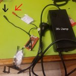
Charger 36v 2amp with tiny 10s balancing bms board connected, arrows show the bullet connectors that go to the 10s 36v battery pack, so the bms board is permanently connected to the chargercharge3.jpg
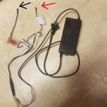
charge4.jpg
PIc below shows bms board connected to battery pos and neg, and 10s connector also attached to pack.
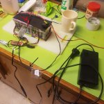
charge2.jpg
So that is all is required to balance the pack.
 
If anyone wants to chime in on how these bms boards work, would be greatly appreciated. I'm assuming that when a cell bank reaches fully charged, its taken out of the charge current by substituting in a resistor to act as that bank, so each bank in the 10s is top balanced.
I could be way off.
I dont want the battery current flowing through the bms mosfets when using the battery on a bike, just need the balancing function which seems to work fine in this configuration with standard charger. since these bms boards are not so expensive these days I think this is good option for budget balancing charger.
 
You can leave the BMS attached to the battery pack permanently even if you discharge directly from the cells' + and - leads. If you want to keep the BMS's overdischarge protection, you can use the BMS output pads to close a relay, contactor, or solid state relay. But if protection during discharge isn't important to you, you can still use the BMS for charge protection and balancing, but bypass it for discharge.
 
I'm assuming that when a cell bank reaches fully charged, its taken out of the charge current by substituting in a resistor to act as that bank, so each bank in the 10s is top balanced.
Not quite, no. When any cell bank reaches max voltage before the others, all charging is stopped via mosfet. The max voltage bank is then drained into a resistor. Then once that cell bank is back down, all charging resumes. That's why toward the end, if your charger has a led indicator, you'll see it switch between charging and not over and over during the balancing phase.
 
And the reason it does that is that if the charger current is higher than a few mA to a few dozen mA at that point, the already-full cell will continue to charge, because the shunt resistor in parallel with it can only divert that much current--usually less than 50mA.
If it's a lot higher than that, like if it's still in the 1-2A or more range, it could rapidly overcharge the already-full cell while the rest of the cells are still in the middle of charging up.

This only happens for badly imbalanced packs, which only happen when there is a large difference in cell properties, such that the overcharging cell has far less capacity than the others, and probably much higher internal resistance.


Anyway, if the BMS doesn't ahve a way to stop the charger from supplying current when the HVC is triggered, this situation can occur.

A sufficiently high current at a sufficiently high overcharge could start a fire....
 
thanks guys, excellent info, yes the charger indicator shows on/off continuously near end of charge, I was wondering why it did that.
Seems all my questions answered. I'm now converted to these bms boards maybe at some stage will use for discharge cycle also.
Looking at aliexpress you can buy 48v14s ( or similar) with balancing for around $20aud includes shipping), thats the cheapest ones,
so not expesnive exercise to convert to a balancing charger at all these days.
 
Back
Top