
whatever
100 kW
- Joined
- Jun 3, 2010
- Messages
- 1,297
I've found the tp4056 boards extremely useful for charging individual 18650 cells, there are two version so of this board, a basic one, and a better one with a couple of chips on it, the more complex board is much better and they are extremely cheap ( around $50c aud per board).
Here is my idea:
use a multitude of these small boards to charge individual cells which are in series, that way each cell will reach same voltage when charged, no need for balancing, it should self balance. Has anyone already tried this idea or suggested this method for a self balancing charger?
outline of how its setup:
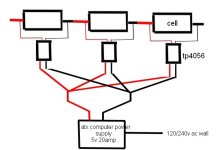
I envisage each cell is permanently connected to its own tp4056 charger, they run on 5v generally. So a 5v power source is required with enough amps to satisfy how ever many of the small charger boards are connected.........in my case it would be 14s pack, so 14 lots of tp4056 required, at 1amp each board that 14amps at 5v, I would imagine plenty of atx computer power supplies would handle that many amps.
potential issues:
the only thing i'm really worried about is some interaction bewteen cells and the charger, making the charger cut off, I use atx power supplies alot and do find using two chargers together sometimes there is some interaction probably since each charger is using same ground via the atx supply.
The max current will be one amp per cell so not suitable for large ahr batteries, but most smaller ebike batteries should be ok, I charge my 24v packs at 1 amp and its fast enough. Some youtube videos do show you can increase the current a bit but some heatsinking of the chips required.
There might be other unforseen issues I'm not aware of.
If anyone has any experience using these boards in this manner please chyme in, I would be surprised if no-one has tried it.
basic picture of the idea below just showing 3 cells but could work for any number of cells in series
Last comment: it would be extremely cheap charger also if this idea works.
Here is my idea:
use a multitude of these small boards to charge individual cells which are in series, that way each cell will reach same voltage when charged, no need for balancing, it should self balance. Has anyone already tried this idea or suggested this method for a self balancing charger?
outline of how its setup:
I envisage each cell is permanently connected to its own tp4056 charger, they run on 5v generally. So a 5v power source is required with enough amps to satisfy how ever many of the small charger boards are connected.........in my case it would be 14s pack, so 14 lots of tp4056 required, at 1amp each board that 14amps at 5v, I would imagine plenty of atx computer power supplies would handle that many amps.
potential issues:
the only thing i'm really worried about is some interaction bewteen cells and the charger, making the charger cut off, I use atx power supplies alot and do find using two chargers together sometimes there is some interaction probably since each charger is using same ground via the atx supply.
The max current will be one amp per cell so not suitable for large ahr batteries, but most smaller ebike batteries should be ok, I charge my 24v packs at 1 amp and its fast enough. Some youtube videos do show you can increase the current a bit but some heatsinking of the chips required.
There might be other unforseen issues I'm not aware of.
If anyone has any experience using these boards in this manner please chyme in, I would be surprised if no-one has tried it.
basic picture of the idea below just showing 3 cells but could work for any number of cells in series
Last comment: it would be extremely cheap charger also if this idea works.
Attachments
Last edited: