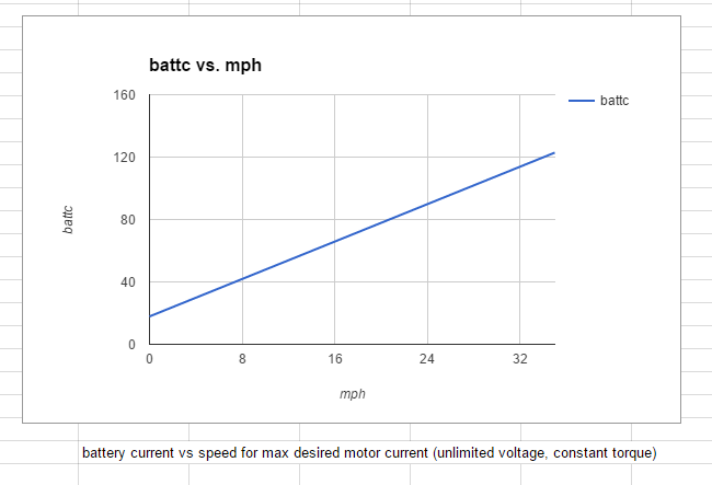
I'm working on the controls for the all wheel drive Novara MTB project, and I decided to check out some of the math that I will be using. The goal there is to make a little black box that will drive both Xie Chang type motor controllers to make the motors share the torque in a reasonable way for all wheel drive. This will be done with two rather different motors, the rear one a 9C direct drive and the front a BMC gearmotor. So I used values for the Cromotor and wrote a few lines of Python to generate some data and then tossed it on a graph to take a look. I didn't graph all the values, only the battery current vs speed (above) to generate this maximum torque. Since it is CroBorg data I though it would be appropriate to reveal it in this thread.
So this analysis is for the battery current it takes at 75 volts to drive the Cromotor with 120 amps (thus constant max torque) versus the speed. I didn't work through the Kv carefully so it is undoubtedly off, but the result looks similar to reality. Amazing how some simple equations and approximate values can reveal so much information.
First of all, based on the motor resistance and the current and 120 amps, the motor heating is over 1300 watts. Since the Cromotor cannot dissipate 1300 watts, it is going to heat up. So putting even 120 amps through it won't work on a continuous basis. But that is the max current I have set for mine (and many folks do more). The other limit I have is 80 amps battery at 66 volts nominal (75 volts fully charged). I chose 120 amps as this is enough to almost lift the front wheel off the pavement. The suspension unloads and if I pedal hard the front wheel bounces. Enough current I think, for a commuting machine.
")
So it takes 11 volts across the Cromotor to get 120 amps based on the 93 milliohm resistance. The controller is converting 75 volts to 11 volts at the zero speed point to generate this 120 amps in the motor. This down conversion in voltage results in an up conversion in current (power is conserved), so the battery current is less than the motor current. In this case it takes about 18 amps of battery current to do this (you can see this on the above graph). The power required is just over 1300 watts, after all at this point we're only heating the motor. No speed, no work being done. So it is all heat. This takes about a 15% pwm cycle, so even if you have the throttle maxed out you're only using 15% (since the controller is properly limiting at 120 amps of motor (phase) current). This is why it is so hard to control a Cromotor at low speed with an old school high current controller, zero to full torque with 15% of the throttle motion is all you've got to work in. A good torque throttle will spread this 15% out over the entire range of the throttle control.
As the speed increases, so does the back EMF, and the voltage required to drive the current into the motor goes up. This increasing voltage load also takes more power (since the current is the same 120 amps all the time) so the battery current also increases to supply this increasing power. We see at just over 20 mph that the battery current hits 80 amps. On this computed scenario the current keeps going up, but on the Borg it stops there and the motor current (which is proportional to torque) begins to drop off. PWM is up to 65% and back EMF is about 38 volts. The battery current at 80 amps is still well below the motor current of 120 amps.
A refreshingly simple look into some of the actual numbers that sheds some light on the details. The math is working.
Note that this does not take into account a lot of details (yet). The back EMF I chose for this simulation is probably low, and there's no allowance for inductance, motor heating, etc that would tend to reduce motor current. The chart above is calculated at 75V but allows the PWM to exceed 100%, so the power continues to increase as if it was a buck/boost controller.
Edit - I just worked out back EMF from motor Kv values and it is close to the estimate I used.