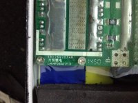
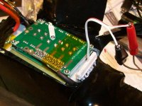
Different voltage from input to output of the BMS

Joined
Jan 29, 2016
Messages
969
Location
Shanghai
Hello everyone,

I have a weird issue on one of my old batteries: 24S LiFePO4

When I connect a multimeter to the output wires of the battery, I read 67V.

But when I measure the voltage from the input of the BMS to the positive of the battery, I read 78V, which seems like the normal voltage the battery should be. So apparently the cells are OK, but somehow, 11V disappear in the BMS.

Any idea what is going on there?
Thanks in advance :)
 
Open circuit V or feeding some load?

Link to the BMS? ideally also to its manual or datasheet in English
 
"low" voltage on hte output usually indicates teh BMS has shutdown to protect the cells for wahever reason (LVC, overcurrent, broken sense wire, bad BMS, etc)

Put a load on the output, and it will generally drop to nothing when this is the case.


If a load on the output doesn't drop the voltage further, then something else is wrong, but only makes sense if there is *already* a load on it sufficient to drop voltage across a high resistance in the output FETs or a poor connection in the power path.
 
That sounds like the BMS is tripped for some reason. With no load and just a meter, there will be a reading through a high resistance on the BMS. If you measure the voltage with a small load applied (light bulb, 1k resistor) it will probably read near zero.
Most BMS will reset if all the cells are in the healthy range and the load is disconnected. I've seen some that refuse to reset with just the load disconnected and you may need to briefly charge through the discharge port or put a jumper from B- to P- to make it reset.

Measure all the individual cell voltages first, then try the reset procedure.
 
Thanks for your inputs folks,

I'll try to explain a bit better the situation:

My scooter battery is divided into two paralleled batteries: the first one is a 72V 30Ah (24s3P), the second one is a 72V 20Ah (24S 2P). Each having its own BMS.

Here is how the first one looks like inside:
The BMS:
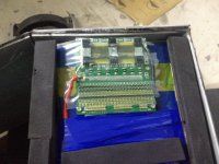
IMG_5967.JPG
The cells connections: Looks sketchy but it worked very well for the past years, and it's beeen beaten pretty hard so nothing wrong with that in the end.
View attachment 4
3 cells are a bit on the low side and started to puff, I'll change them
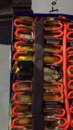
IMG_5970.JPG

This first pack works well, when I connect a voltmeter to its ends, I get the same reading as before the BMS. Just have to change the defective cells and it should be good to go again.

Now, the second pack:
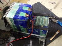
IMG_5973.JPG
The BMS:

IMG_5977.JPG

The reference appears to be LH-HP24SA V1.0

I haven't measured all the cells individually yet, because, as you can see, they are pretty hard to access to. But I'll try to do that soon. But the total reading before the BMS seems to be coherent with what it should be.

The problem I have is on this second battery: I get a different voltage reading before and after the BMS.
Before: 78V
After: 67V

I thought about a BMS shutoff, but generally when this happens I just have to connect the battery to the charger for around one minute and it's back again. So i did try that, the battery seemed to charge normally, but after disconnecting the charger it still have this 11V difference. I didn't put any load on it yet so I will try that, but the BMS seems alive to me, usually when it shuts off I read around 0V or maybe 2-3V. Definitely not 67.

What puzzles me is that the first battery doesn't seem to behave at all the same way. First one behaves totally normal.

Anyway, I'll do some more tests, but if anyone has any clue about what might happen here feel free to give me any leads. :)
Thanks!
 
Dui said:
I haven't measured all the cells individually yet, because, as you can see, they are pretty hard to access to.
Not really--all the cells are accessible via the BMS balancing/sense wires (and the main + - pack wires for the end cells, if there arent' separate sense wires for that).
 
amberwolf said:
Dui said:
I haven't measured all the cells individually yet, because, as you can see, they are pretty hard to access to.
Not really--all the cells are accessible via the BMS balancing/sense wires (and the main + - pack wires for the end cells, if there arent' separate sense wires for that).

Yep, That's what I thought I'd do, but it implies to trust the BMS wires good health and also I'll have to remove the protective coating from the board while making sure I don't short two cells so that's not super easy.
 
No need to remove any coatings, and using the sense wires helps you verify that *they* are also working (if the cells are good and the sense wires are not, then the BMS will still have an error). If you find any that show 0V, then you can test that specific wire to it's cell end connection.

To test without removing coatings, then make sure your probes are very sharp and pointy. Use a bit of heatshrink or insulation stripped from wires, etc., to cover the entire probe tip all teh way to the point, but not beyond it. Push the tip into the coating till it reaches the soldered pad. Even if you slip, the probe tip is covered, so it shouldn't be able to short to the other probe, etc.

Or, if you can unplug the sense wires from the BMS, you can use two bits of thin solid (not stranded) wire as probe tips to go into the connector holes. This is also a fairly short-resistant method. (fechter has pictures of this method in some of his battery-testing help posts).
 
amberwolf said:
To test without removing coatings, then make sure your probes are very sharp and pointy. Use a bit of heatshrink or insulation stripped from wires, etc., to cover the entire probe tip all teh way to the point, but not beyond it. Push the tip into the coating till it reaches the soldered pad. Even if you slip, the probe tip is covered, so it shouldn't be able to short to the other probe, etc.

Oh, the heatshrink is a neat little trick, thanks :)
:bigthumb:
 
Here's the picture

Single Cell Charging Hookup 2.jpg

This requires unplugging the balance connector, but this should be avoided if possible as you can sometimes blow the BMS hooking it back up. Using the same probe wires, you can generally back probe the connector without unplugging it.

Another approach is like Amberwolf says. I have a set of meter probes with sharpened tips. These can poke through the conformal coating on the board and you can just measure along the connector.

All it takes is one cell to be low to trip the BMS.
 
Well as it turned out the battery had no problem at all, it was just discharged a bit too much.

I first took the BMS off and opened the battery to get readings directly from each tab. They were all pretty consistent (3.28V) except for one group which was quite a bit lower than the other ones (2.7V). Plugging back the BMS wires apparently seemed to reset it, so I was getting normal voltage readings at that point.

I had it charged back and everything seems fine now. All the cells seem to be pretty much in balance, but I guess one group of cells is a bit at the end of its life so I'll replace it with fresh ones.
 
Back
Top