flangefrog
1 kW
I just finished building a spot welder based on KaeptnBalu's design. My build log starts on page three of the Aussie DIY spot welder thread: https://endless-sphere.com/forums/viewtopic.php?f=31&t=80315&p=1215403#p1219530


So, we want to concentrate on changes/improvements that will reduce the importance of selecting the right size battery, for example. Too small a battery and you'll be limited to welding very thin metal, or not at all, while too big a battery and you might exceed the peak current rating of the MOSFETs, or their avalanche energy rating (if no freewheeling diode is present on the MOSFET board - not dangling in the middle of the welding cables somewhere... ahem).
In that spirit, then, I would say that adding a freewheeling diode is mandatory, but the input capacitors can probably be dispensed with, especially if the suggestion I'll give below is implemented.
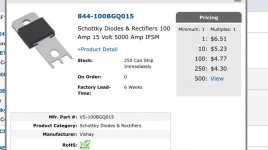
For the freewheeling diode, part number 100BGQ045 part number that okashira suggested a few posts back is superior to the MBR8020R I suggested, both in peak current rating and cost.
The original spec'ed MOSFETs - (AU)IRF1324 [the AU prefix means Automotive rated and is optional] is a really good choice, though I'd probably bump that number up to (8) in parallel so there isn't such a worry with the size/ampacity of the battery.
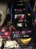
I would design the board so that it bolted onto the negative post of the battery and used a short-as-possible jumper to the positive post comprised of 5-7 #14AWG insulated wires wire-tied together. Doing this, rather than using a single larger diameter wire, will put the stray inductance of each wire in parallel, which will reduce it by the inverse of the number of wires paralleled (ie - down to 1/5th or 1/7th), and the lower this inductance the less need - perhaps no need at all - for decoupling capacitance (though as I mentioned before I consider this bad engineering regardless). Also, 5-7 #14AWG wires will be cheaper and easier to obtain than a single #4-#6AWG wire, and they will be easier to solder (in individual holes) to the PCB.
I would use a stronger gate driver IC - I'd like to see at least 4A peak here - and lower the value of the gate resistors accordingly. For example, MIC4420, a 6A driver for $0.95-US, and 22 ohm resistors for each MOSFET (whether 6 or 8 are used).
One of the minor changes I would make is to get power to operate this circuit from the 12V battery by using a blocking diode and a bulk storage capacitor so the circuit still functions while the battery is delivering welding current. There are undoubtedly a few other things that I would do differently, but this is already turning into a proverbial "Homer's catalog of ships" (re - The Iliad) so I'll leave off for now.

flangefrog said:Here is a new prototype spot welder probe. Using 6AWG silicone which is probably fine but I'm going to try to buy some 4AWG silicone. It's much more flexible than the neoprene rubber insulated cables I was using.

calebleemcd said:Flangefrog, did you ever compare the difference the alternate tvs and flyback diodes made? I'm Auckland based and have access to a Digital scope if you wanted to do some testing.
Do you have any spare PCBS for the spot welder?


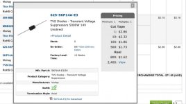
I think two schottky and three TVS diodes would be the max you need. Even just one of each or only a schottky will help.