DIY MOT spot welder for 18650 cells

Guys, you gave me all the information I need it and I thank you for that.

Now all I have to do is to build the welder. I've ordered the parts and soon I will write here how all things went.

Meanwhile I have to rebuild the MOT with bigger wires.
 
Hi,

I've done the welder :)

I've posted pictures with my first welds, how they are? I ask this because they are colored and I don't know if it is ok this. But they are very strong.

Thanks!
 

Attachments

  • 20151119_151500.jpg
    20151119_151500.jpg
    148.3 KB · Views: 2,136
  • 20151119_151608.jpg
    20151119_151608.jpg
    269.2 KB · Views: 4,147
bikegeek said:
Hi,

I've done the welder :)

I've posted pictures with my first welds, how they are? I ask this because they are colored and I don't know if it is ok this. But they are very strong.

Thanks!

It's a bit hard to tell but it looks like the current/time is set too high and the nickel has been vaporized at each weld. You want to set the current/time just high enough so that when you rip the nickel off the battery every weld gets left on the battery and creates a hole in the nickel.


Do you have any pics of your welder?
 
And the welder.
 

Attachments

  • 20151119_153052.jpg
    20151119_153052.jpg
    177.1 KB · Views: 2,564
  • 20151119_153101.jpg
    20151119_153101.jpg
    170.9 KB · Views: 2,564
  • 20151119_153108.jpg
    20151119_153108.jpg
    148.2 KB · Views: 2,564
  • 20151119_153131.jpg
    20151119_153131.jpg
    180.8 KB · Views: 2,564
  • 20151119_153151.jpg
    20151119_153151.jpg
    132.6 KB · Views: 2,564
Now you're talking!!
I agree with FF, it looks a touch over done- inspect the welds closely... If there is a significant depression, or a circular crack around the weld or even blow through its too much current/time. You want a nice uniform dot that welds strong enough to tear a hole in the tab when you pull it off.
Too much current is good- turn the time down.
Not enough current is not so good because a longer pulse=heating.
A small amount of discolouration around the weld is OK, but you want to try and keep away from excessive blueness all around the weld site. Too much heat.
Practice lots and well done on the upgrade!
 
Hi guys,

I want to write a review of my welder. I had some problems and I've made some modification. Maybe I will inspire others.

1) The Micro Arduino is not working with 9 V battery. Now I'm powering the Arduino with a mini USB charger from 220V. The mini USB port is working OK.

2) The tips were made out of 6 mm cross section wire. Very soft and they were melting fast. I had to file the tips during the welding of an 40 cell pack. In the end I replaced them with 6 mm in diameter copper bar. Much durable and rigid.

3) Flexure in the wooden arms. I replaced them with 20x20 mm aluminium bar that I had laying around.

Secrets:

1) The two arms are electrical separated because they are fixed together by a plastic screw. The green one.

2) The two arms are also electrical separated because I used copper clad board to separate them from the aluminium support between them.

Info:

The space between the tips is 3mm.

I can weld nickel 0.15 very easy with 40 ms first pulse and 80 ms second pulse.
 

Attachments

  • 20160119_185959.jpg
    20160119_185959.jpg
    121.5 KB · Views: 4,085
  • 20160119_190041.jpg
    20160119_190041.jpg
    98.2 KB · Views: 2,560
  • 20160119_190033.jpg
    20160119_190033.jpg
    74.3 KB · Views: 2,560
  • 20160119_190026.jpg
    20160119_190026.jpg
    110.8 KB · Views: 4,085
  • 20160119_190020.jpg
    20160119_190020.jpg
    118.8 KB · Views: 4,085
  • 20160119_190013.jpg
    20160119_190013.jpg
    96.8 KB · Views: 2,560
  • 20160119_190006.jpg
    20160119_190006.jpg
    95.1 KB · Views: 2,560
  • 20160119_190238.jpg
    20160119_190238.jpg
    116.7 KB · Views: 4,085
  • 20160119_190229.jpg
    20160119_190229.jpg
    78.7 KB · Views: 2,560
  • 20160119_190218.jpg
    20160119_190218.jpg
    80.5 KB · Views: 4,085
  • 20160119_190105.jpg
    20160119_190105.jpg
    79.8 KB · Views: 4,085
  • 20160119_190057.jpg
    20160119_190057.jpg
    101.5 KB · Views: 4,085
Should I go with 00AWG, 0AWG, 1AWG, 2AWG, 4AWG or 6AWG+ when building a MOT spot welder?
I have easy access to these guages except 3AWG, sold by the foot.

Also wouldn't it be better to just do one or two wraps to get the most current possible?

How do you know which winding is the primary and which is the secondary when taking apart a MOT?
I ground down the welds and got my ~1100W MOT apart (easier then hammering and chiseling the windings out), I have one half which is larger wire, other half is smaller wire.
 
The bigger the wire the better it is. But you have to choose a wire that is flexible too and that fits your MOT. I used 16mm (5 AWG) copper wire and works great.

My wrapping is called 1.5 turns. I think it is enough. If you use very thick wire you will not be able to do more turns.

The primary is the coil with thick wires. The secondary is the one with thin wires. You have to keep the one with thick wires.
 
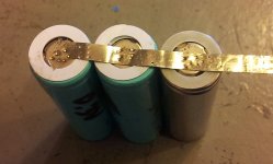
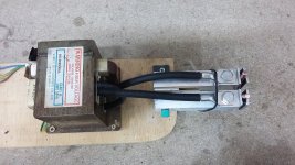
Thanks, I kept both windings, I figured the thicker wire winding is the one I needed.
Do I have to pay attention to the way the windings wrap? and do the same with the added welding cable wrap?

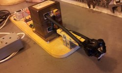
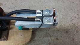
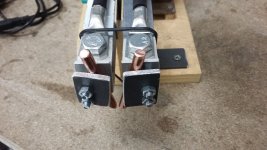
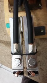
At Princess Auto (Like USA's Harbor Freight) all they had was 0, 00, 1, 2, 4, 6. Ideally I wanted 3awg, I was 50/50 whether to buy 2 or 4awg. I ended up buying 2awg and its huge. I think I made a mistake, hopefully I can return the welding cable and buy 4awg, but only if its necessary to get more wraps. The only other wire I got on hand is 8AWG.

What do you guys think?


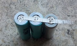
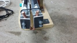
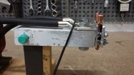
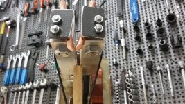
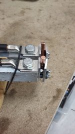
I can only get about two turns, I think ideally I need 3 turns, from what I gather from this website
Use a flexible 3AWG / 25mm2 welding cable with a length of 140cm, this allows 3 windings. I have examined if a thicker cable give a higher weld current, this was not the case. The weld current is limited by the transformer itself.
but if your 1.5 tuns works then my 2 should be fine.

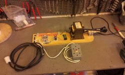
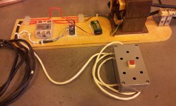
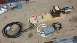
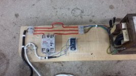
I am using a timer, from the avdweb.nl website. Its all ready to go.
1mot 2AWG.jpg
3MOT 2AWG.jpg
4MOT 2awg.jpg
2MOT 2AWG.jpg
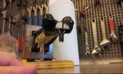
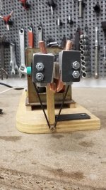
I will epoxy on the top and clamp it over-night.
 
bikegeek said:
And the welder.

So you bought these items did you?
bikegeek » Sat Oct 10, 2015 1:53 am
Kdog, what type is your timer?

For now I found this on ebay:
- arduino: http://www.ebay.com/itm/NEW-UNO-R3-ATme ... 48724e5e0c
- http://www.ebay.com/itm/24V-380V-SSR-40 ... 3398dbc69d

solid state relay with a 555timer SSR can run directly off output of 555.


I am copying the guy from advweb from the Netherlands, but without the power resistor and bypass switch, thats used for "sensitive components", might do my arms in wood. I am concerned about using aluminum U channel. I see you bolted the wire straight to it with your mentioned isolation between the two arms. I will do mine in wood or plastic. I want it to be ultra-safe.

Interesting build, as long as it works and its safe then its all good.

I will probably enclose mine, and put some fans in it.
 
I think is more than enough for the wire. If you have 1.5 turns or 3 is not a big difference. I would choose the biggest wire for more power than a smaller one for more turns.

It dose not mater how you put the coil if you work with AC.

All the parts were bought from eBay, except the MOT.

It is hard to do the arms from wood and have 3-4 mm distance between electrodes. But my design is just one way to do it, I used the things I had in house.
 
I got a little bit of a hiccup here.
I have 2AWG welding cable wire, and the conductor is massive while my pure copper rod with its holder is small.

Is it wise to snip off some strands of wire on the 2AWG welding cable to make it fit, or should I find another solution.
I might just do it your way with the cable lugs/crimp: looks smart and is neat and clean.
Instead of clamps or elastic bands, I will use some weights on each arm.
http://www.princessauto.com/en/detail/2-pc-4-to-1-solder-crimp-welding-cable-lugs/A-p8509887e


I do find that I am having a problem getting the distance to be as small as possible with no touching between the copper electrodes.
 
Depends how obsessed you are with the welder. If you remove some strands it will work perfectly but if you want it to look nice you have to find another solution. Change the cable or do like flangefrog recommended drill a bigger hole, remove strands and use heat tube to isolate and make it look nice.
 
Hi bikegeek, I'm started my own spot welding machine proyect and I'm very interested in yours, but I'm a newbie in this stuff, so could you put a basic wiring diagram of your spot welder proyect? (including arduino PCB and SSR relay in/out).
Have you finally used the components you said in the board?
by the way, what is the purpose for this grey box?, it's a switch to activate the welder?.
 
Bikegeek, Thank you very much for the wiring diagram. :D

I've almost finished my own spot welding proyect, I'll put some pictures after.
 
In order to carry high current, while still having probes that can actually work, I'd like to suggest using very thick copper rod for the majority of the two probes, and then having two thinner rods "hose-clamped" to slots on those thicker rods. That way the skinny part that actually touches the nickel strip is easily replaceable.

I'm also told the center of the 18650 cell-tip is not the place to locate any of the welds, Imagine a circle, halfway between the perimeter of the button , and the center, and that is the area where all welds should be located.

It also helps consistency to have a slot down the center of the paralleling strip, which forces all of the spot-welding current through the cell-tip (as opposed to some of the current passing through the strip itself, from one welding tip to the other, with less flowing through the cell-tip)
 
I am having a hard time soldering tabs onto my used a123's so the slot idea would totally work. Thanks for that remind SP, I have seen it done on others rigs as well.
 
p1.jpg
Hi guys,
I was trying to make a battery set of 18650 myself and found it is not possible to weld them with iron welder
then I found bikegeek did this spot_welder here so thanks him I made a copy of it
I am not finished it yet, because I have problems need help
the Arduino code work great and the ssr also blink twice when I pushed the button
but don't know why The SSR suddenly become short for all time on the AC side
first time I thought I got a bad SSR so I bought another one but the second one went short on AC side also
if I guess the OVEN is 1000 Watts than W=V*I the power voltage of my country is 110V then 1000<110*10 so the current should less than 10A
IS the SSR mark 25A still too small for this case?
thanks for the help in advance

I replaced a 40DA SSR and added a switch in the input side of SSR to prevent auto switch on when the Arduino first bootup then everything work perfect thank you all
 
Hi Everyone. I built a MOT spot welder a while ago for just everyday spot welding, and I decided to add a timer circuit to it using Arduino etc
My problem is the SSR
So far I've killed two of them. They were the Photek 40A. They died after being activated once or twice while connected to the transformer. Now they are a constant ON
I know that there are many "knock off" of SSR and perhaps that's why they went.
From what I have read, when using a SSR with inductive loads you should use a Random On SSR, not a Zero Crossing one. All those Photek are Zero crossing
Also note I am in Australia so I'm 240v I think it was a 1100w microwave. The transformer doesn't say much on it and I cant find the model number online

I have a few questions.
1) Do i need to get a random on / non zero crossing SSR? is that essential? seems not many people are using them
2) Is there any protection circuit stuff I should put on the 240v side to help protect the SSR?
3) In the microwave there was a small circuit board with a few huge resistors a coil etc which I assume is some sort of filter? I had been using that, perhaps I shouldn't? (this is it here: https://goo.gl/photos/odyewdhhrmB1JKKt9 ) NOTE: The FIRST SSR that died was wired in between this board and the transformer. I wondered if this might have lead to its demise so... I put the SECOND replacement SSR before this board and that one died too. Grrrr...
4) any recommendations for SSR? (Ones that are good for more than one weld haha)
5) Does it make any difference / damage if the SSR triggers the transformer with or without something being spot welded?

I've been thinking about getting a 480v 80a ssr, but not sure if I should get a random or zero crossing one. zero crossing ones are a lot easier to find.

This is the controller part
https://goo.gl/photos/1sd7M4r1DaKDwRdF8

This is the transformer
https://goo.gl/photos/cfWZtrbu5MmCJoqL6
and
https://goo.gl/photos/B8ax28dH9rGLaX4v6
And yes the shunt is still in there


Love to hear your thoughts

Cheers, Marty
 
Hi Marty,

Nice welder you are building. That was my plan too, to add a display and a dial and not to use the computer to change the time. But i'm not that good at arduino and the friend that helped me is busy now. Maybe you could share you design because I would like to make it nicer and not use the computer :)

I would recommend to use the transformer just like that, without the circuit board. My welder is very simple and just wires. I would recommend to make some sort of metallic shield for the ssr and arduino. And also to test the ssr without connecting it to the transformer. If if works than is the transformer that is destroying it.

For the ssr I used the cheapest I could find on ebay.

Catalin
 
I also had some problems with the power supply for the arduino. When I was using 9V it was freezing after a few welds. So I now use a 5V usb power supply.
 
The only thing I can think of with regard to the SSRs dying is that it's probly best not to use a really low activation voltage. I use 11v ( or there abouts) I don't really know but it might help turn them on quicker so the semiconductor isn't in transition for quite as long, trying to dissipate several thousand watts. Other than that maybe it's like anything- you get what you pay for. Cheap eBay SSRs are not likely to be as good as brand name ones that cost 10x more ( even though it's probly mostly the name you pay for)
Mine has done thousands of welds and lots of tests wo a load, no filter and it's stil going strong ( touch wood). Although it doesn't like getting hot. The sun was shining on it little plexiglass housing and it really heated up, I lost power but when I cooled it again it was fine. I did pay $40 for it at the local electronics shop which I was spewn about at the time but maybe now it's paid off 8)
 
Back
Top