E-brake/OPTO Isolator circuit assistance needed!

Joined
Jun 26, 2023
Messages
9
Location
VanCity
My current electrical setup is as follows.

“E-bike”:
-72V 25Ah 1800 Watt-hours
-Phaserunner L10
-V3.1 Cycle Analyst
-Grin All-axle front hub
-E-brake levers with micro switch

Lighting (12V):
-DC/DC Converter
-ON/OFF toggle switch (for the 12V output of the converter so that the entire light/accessories circuit can be toggled on and off)
-Main Control switch (DTR/Headlight toggle, left and right blinker independent toggle, horn)
-x2 Headlights
-x4 LED light strips (x2 left blinker and x2 right blinker)
-x1 Brake/tail turn light (DTR, left and right blinkers, and brake)
-x2 LED flashers
-x1 OPTO Isolator (to control the brake light with micro switch signal)

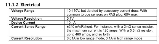
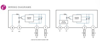
The OPTO Isolator I am using is the CX240D5 and the technical info is at:


I am a very much out of my element and haven’t touched low voltage since middle/high school and am a little rusty. I have everything working except the brake light. For some reason no matter what I try I can’t seem to be able to sort out what I’m missing. Please correct me if I am wrong at any point!


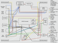
Below is a “schematic” I tossed together to get the general idea.

IMG_0020.png


The current brake micro switches are 0-5V active high. By using the OPTO isolator it’s keeping the 12V and 0-5V circuit separate; therefore, allowing the 0-5V e-brake signal to safely be used to control the 12V brake light.
The active high status of the e-brake 0-5V signal with this OPTO relay work as it has a zero voltage turn on. Knowing the 0-5V e-brake signal doesn’t have enough current to supply the OPTO isolator it would require a pull up resistor to be able to supply the correct current for operation. (~200-330ohms)

I have tried to wire this relay up every which way from Sunday and I have not been able to get it to work. I had thought given the constant feedback I was getting on the Cycle Analyst screen that I must have had a ground fault going from bench test to wiring it up on the bike (relays were still stuck in shipping so I decided to wire it all up on the bike except the brake light line and relay, ahead of time).

I’ve cut into my harness and I’m now basically back to a bench test to eliminate the possible ground fault. Still not success. I currently have my 12V accessory switch and Main Control switch hooked up to the flashers and the rear brake/tail lights (which will allow me to test all but the horn which I know already works).
Without the relay in everything works perfectly just the way it should. As soon as I try to hook up my control side of the relay I get increased brightness on my CA and not the correct function or voltages at the relay terminals and brake LED.

I assume I must not being installing the pull up resistor properly. Given I have the v3-CA I just took my 5V off the unused pin of the e-brake plug. I did read in another old thread/post about someone pulling off of the Aux or Throttle Control lines, I tired that too and I am getting the same results.

Can someone, anyone please help me make my brake light work! =D
 
AFAIK the ebrake inputs on the CA are active low--they work when grounded. If your levers are not wired to do this, it might be why it isn't working.


If your opto requires a high signal to operate, then it will turn the brake light on all the time except when you use the lever.


For my SB Cruiser's "12v" (really 16v max, 4s NMC pack) brake lights, I didn't use any optos, I just used a direct 5v-coil relay (three of them, actually) with coil powered off the CA's 5v line (from the throttle, IIRC), and the ground side of the coil connected to the ebrake lever's signal line. The ground of the signal line goes to the CA ground.

The brake light relay has common pin to the lighting power system ground, and NO pin to the brake light ground. Lighting power system + goes to the brake light +.

Pulling the brake lever closes the NO switch inside it, grounding the coil of the relay(s) energizing the coil, pulling the relay in and closing the NO contact of the brake light relay, grounding the brake lights and turning them on.


My other two relays are used to ground the CA's ebrake input, isolating it from the relay's coil feedback (which also have diodes on them to minimize that) and switch which cable-operated throttle is used to feed the CA's throttle input, so that the brake-lever-pulled-throttle controls proportional regen strength and the regular thumb throttle controls forward traction power.

But the CA appears to have enough current on it's 5v line to run both COTs and three tiny relay coils in parallel.

Any optoisolator I've worked with uses teensy tiny currents, far less than a relay coil. If you are powering the opto board off of the 12v line, the CA doesn't even need to supply any current at all--it only has to sink the current for the opto's LED inside the opto chip (a few mA at most, probably less). If you are powering the opto's LED off the CA's 5v line, then it only has to supply that tiny few mA or less, and only when the LED is grounded by your ebrake switch. (or powered by the switch if the opto has an active-high input, and you wire your ebrake switch from 5v to opto LED input to supply that when the switch is closed by pulling the lever)


If your ebrake levers are NC switches, you might have to use the NC output of the relay or opto.
 
I apologize, you are correct I made a mistake when typing it out. The brake levers are NO active low.

My reason for the OPTO Isolator is it the crydom is super tiny and waterproof, given my space requirements it seemed to be the best route/option even though I have never used one before. I know it can be done a few other ways, but this should be able to work, no?

I thought the pull-up had to be on the control side as on the spec sheet the 0-5V line of the CA has only 10mA and the typical operating range for the control side of the OPTO Isolator is 15mA. On the Load side it just states a minimum load of 0.06A to a maximum of 5A.
Or have I been wrong this whole time and I should be pulling up my constant 12V on the load side?

Attached is the wiring diagram for the OPTO Isolator if it helps any:
 

Attachments

  • IMG_0021.jpeg
    IMG_0021.jpeg
    262 KB · Views: 7
My reason for the OPTO Isolator is it the crydom
What is a "crydom"?

is super tiny and waterproof, given my space requirements it seemed to be the best route/option even though I have never used one before. I know it can be done a few other ways, but this should be able to work, no?
It's the same principle as the relay, just solid-state, so yes, it should work as long as the voltages and currents of all the parts are within each other's limits.


I thought the pull-up had to be on the control side as on the spec sheet the 0-5V line of the CA has only 10mA and the typical operating range for the control side of the OPTO Isolator is 15mA.

15mA? That seems gigantic for something like that, maybe half a dozen times what I would expect.

I don't know the current of the relays I'm using, but three of them in parallel aren't exceeding the CA's ability to drive the coils (plus a hall-based PAS sensor, and two hall-based throttles).

It must be powering the whole control circuit, not just the LED, from that 5v input to get that kind of current draw.

An opto should only power the LED from the control side. The other part should be powered from the controlled side, if it requires power at all. (they don't normally)

Normally an optoisolator is just an LED that activates the base of a transistor, and the collector and emitter of that transistor are on the controlled side, totally electrically isolated from the LED. You connect the emitter (for NPN) to ground, and the collector to the ground side of your load. Your load's other side connects to the load power supply (12v in this case).

Then you put current thru the LED, it turns on the transistor, and that grounds the load and the load does it's loady thing ;) and it just works.

High current ones or ones intended only to switch a load and not variably control it often use darlingtons on the controlled side.

1688016033113.png


Based on the DC verison in your posted "wiring diagrams" image, all you should have to do, given that it already has series current limiting resistors shown inside the opto for the LED inside it (control input), is to wire the +DC LED (anode) to the 5v line (of the CA, if that's your only 5v source, or the controller's 5v if that's got more available, or a separate 5v DC-DC powered from your main battery if that's your only option), and the -DC LED (cathode) to the brake lever's signal line, which also goes to the CA's brake input if you're using it for that, too. Then the brake lever's ground wire goes to the 5v ground.

If you like you can insert a series resistor between the LED and the 5v supply, to limit current further. You would need to check the spec sheet for the opto's LED minimum turn-on current that fully turns on the control output, or experiment using a potentiometer to find the trip point, and use that resistance value (or lower). That will economize the current used to do the task, lessening the load on the 5v supply.

There are lots and lots of different models of optocouplers / optoisolators, with different purposes and specs. You don't need a fast turn on or turn off time; the slowest available will work for you. You just need one with an output stage that can handle the worst-case load current of your lights, and the worst-case voltage peak the lighting supply could ever have on it, and with a high current-gain ratio between control current and output current (so you can use as little current as possible to drive the LED while having full turn on of the output.


However....the diagram picture shows both versions are AC controls, they are TRIAC outputs, and those won't work properly to control DC, because they will latch on and never turn off because the power source never does the zero-crossing / polarity reversal that AC does.

If your actual opto-control part is a DC-type control using a FET or some other solid state switch, then it should work by connecting it to ground your brake lights, or by powering them. (I always use control switches to ground a circuit (vs supplying voltage to it) if I can, becuase it usually simplifies the switching circuit, especially if it's solid-state...but I do it with relays too because it's easier to remember just one way of wiring things. ;) ).

(IIRC I used relays out of a trashed UPS (battery backup for a computer) for my system on SBC. Maybe I'll try some optos on a bench test of the same type of system to see how well they work (cuz they'd be a lot smaller)...but I doubt it will be anytime soon. If I do, I'll probably pull them out of dead SMPS systems if they are DC-control types (vs AC). Old computer PSUs are the likely first donors, as I don't think I still have that old UPS board (it had some optos on it).
 
What is a "crydom"?
It’s just the name on the OPTO Isolator, I assumed brand name.
If your actual opto-control part is a DC-type control using a FET or some other solid state switch, then it should work by connecting it to ground your brake lights, or by powering them. (I always use control switches to ground a circuit (vs supplying voltage to it) if I can, becuase it usually simplifies the switching circuit, especially if it's solid-state...but I do it with relays too because it's easier to remember just one way of wiring things. ;) ).
Perhaps that is the issue I am running into, my “wiring diagram doesn‘t convey that the rear light it a combine board with DTR, blinkers, and the brake/tail light leaving my ground having to be connected to the my main spider.

Essentially I think this relay isn’t quite the perfect fit. I swapped it out for another from OPTO22.com. It‘s the G4 ODC5R, this version has 5 pins vs. the 4 pins on the other one I was using; therefore, eliminating any issues with my wiring of the pull up resistor.
This is the link for the download of the spec sheet for this series of OPTO Isolators: Opto22 - 0364 G4 Digital Dry Contact Output Modules Data Sheet

IT WORKS!!! Sort of..

Every time I activate the LED it functions like it should during both normal and DTR operations; however, the problem I am running into is my CA screen is getting an increased brightness every time the circuit is closed and the LED is activated. I had assumed that this issue would be negated by not using the pull up resistor.
Would that mean my logic voltage or current rather is crossing over to my control Inside the relay? Do you know of anything I could do to remedy this? Would it be as simple as perhaps adding a diode on my control line at the relay pin?
 
It’s just the name on the OPTO Isolator, I assumed brand name.
Ah. I looked up the name as a brand and it does come up.

Perhaps that is the issue I am running into, my “wiring diagram doesn‘t convey that the rear light it a combine board with DTR, blinkers, and the brake/tail light leaving my ground having to be connected to the my main spider.

As previously noted, If you are using the part that the diagram you've given is for, then at least part of the problem is that it's for AC use, not DC use, and you'd have to get the DC version.


I swapped it out for another from OPTO22.com. It‘s the G4 ODC5R, this version has 5 pins vs. the 4 pins on the other one I was using; therefore, eliminating any issues with my wiring of the pull up resistor.
This is the link for the download of the spec sheet for this series of OPTO Isolators: Opto22 - 0364 G4 Digital Dry Contact Output Modules Data Sheet

Just to make sure: There are two versions.
G4ODC5R
G4ODC5RFM*
G4ODC5R5
G4ODC5R5FM*
the left one is NO, the right is NC. Presumably you want an NO switch, so it stays off (disconnected) except when activated. This would be the G4ODC5R (vs G4ODC5R5)

Either way, the input works like this
Logic OFF voltage range​
VDC​
0.0–0.8​
0.0–0.8​
Logic ON voltage range​
VDC​
3.8–6​
3.8–6​
So it works the opposite way you want it to. It will turn *on* when the brake is *off*, and *off* when the brake is *on*, because your brake switches are active-low.

If you use the G4ODC5R5 (NC output) version instead, it would do what you want.

However, it still takes a (relatively) huge current to operate it, compared to what you have available, and that is probably why it is changing the CA screen brightness. (would need to see your complete wiring diagram to understand what your current paths actually are)
Logic input current at
nominal logic voltage​
milliamps​
14​
14​

An opto for your purpose probably needs to be much lower current, like a tenth of that, given the 5v regulator's current that's available per your previous post. (you'd have to test to see how much current all the things connected to the 5v line are actually using, without the opto, and then measure how much the opto itself uses by itself without the other stuff connected, and add those together to get the actual loading on the CA during use.)


BTW, if your lighting system and your CA / traction system share any common wiring (ground, etc) then they aren't isolated, and various wierd things can happen depending on the exact current paths you have when various things are active or not.
 
As previously noted, If you are using the part that the diagram you've given is for, then at least part of the problem is that it's for AC use, not DC use, and you'd have to get the DC version.
For some reason I thought I had the DC/DC version. I think that’s why I was getting so infuriated that something so simple wasn’t working like it should be… *sigh*… *face palm*.
If you use the G4ODC5R5 (NC output) version instead, it would do what you want.
I tried the G4ODC5R5 as it was what I had on around to play with/test and it ended up working backwards due to the relay being NC and the switches being NO, I assume? Once I was able to swap over to the G4ODC5R with NO matching with the NO switches it worked just fine, minus the feedback on the CA screen. (I should note for future diagnosis efforts that the feedback on the CA screen occurred with either relay, the only difference between the two seemingly being the correct condition/operation with the brake lever and brake LED.

I got a little confused with this spec sheet in regards to the Logic On/Off. I understand what it is and what is means; however for both the NO and NC versions they are the same and I assumed that the values would reverse, dictating whether or not it was zero voltage turn on or not (active high or low). Yet in this spec sheet they are the same across the board.
However, it still takes a (relatively) huge current to operate it, compared to what you have available, and that is probably why it is changing the CA screen brightness. (would need to see your complete wiring diagram to understand what your current paths actually are)
Logic input current at
nominal logic voltage​

milliamps​

14​

14​

An opto for your purpose probably needs to be much lower current, like a tenth of that, given the 5v regulator's current that's available per your previous post. (you'd have to test to see how much current all the things connected to the 5v line are actually using, without the opto, and then measure how much the opto itself uses by itself without the other stuff connected, and add those together to get the actual loading on the CA during use.)


BTW, if your lighting system and your CA / traction system share any common wiring (ground, etc) then they aren't isolated, and various wierd things can happen depending on the exact current paths you have when various things are active or not.
I will work on sketching up an accurate diagram to the best of my ability to include all components and wire paths right away. Basically all I did was make a new JSP connector for the 4 pin of the e-brake (which pin 1 and 3 are used for the brake handle micro switches 0-5V digital signal, ground and then pin 4 I believe had the 5Vcc) and pulled all 3 of those straight back to the 5V logic side of the relay. Each going to its own respective pin of the relay.
I completely understand that they are, in the grand scheme of things connected when it comes down to it (ie.sharing the same main power source and ground). I read somewhere on some electrical forum about it being beneficial/safer when you can to keep grounds separate, so all I tried to do was keep my two systems as “separate” as possible (Ie. all 5V and ground togethers and all 12V and grounds together, etc. and so forth).

As mentioned I will get a complete diagram with all components and wiring paths together with urgency. I would do it right this moment but I just did 95km yesterday and another 80km today, so I am due for some quality time with my pillow. I will get at it first thing in the morning!
 
For some reason I thought I had the DC/DC version. I think that’s why I was getting so infuriated that something so simple wasn’t working like it should be… *sigh*… *face palm*.

I don't know which part you have, but the diagram you posted for it is the AC type, with TRIAC / SCR type output, instead of DC open-collector transistor. See the opto-types diagrams I posted in that reply for what they look like schematically. (physically, both opto chips look the same outside, it's only in the internal silicon that they differ, so you have to check the part number you have with the manufacturer spec sheet).


EDIT: I forgot you did state you have the CX240D5, which is listed as
"SCR output for heavy industrial loads • AC or DC control • Zero-crossing (resistive loads) or random-fire (inductive loads) output"
so the *control* side can be AC or DC (as long as the LED lights up it doesn't matter if you're using AC or DC for it; the AC-control version probably has internal filtering on the detection of the output side to smooth out "ripples" in the LED output (which will reduce it's response time).

Your specific one has DC-input-control, but the output is still an SCR, which means it won't turn off until the output current drops to / below zero. (which won't happen on DC until you turn the power to it off; on AC it would happen twice every cycle of the AC frequency).


Description CX240Dx
Nominal Voltage 5 VDC
Control Voltage Range 3-15 VDC
Minimum Turn-On Voltage 3.0 VDC
Drop Out Voltage 1.0 VDC
Typical Input Current 15 mAdc

If the relay does turn the lights on when you pull the lever, it just about sounds like your switches *have* to be NC instead of NO? (assuming you are wiring the input to the control pins on the opto so one opto pin is grounded with the brake lever's ground, and the other opto pin is connected to the brake lever's signal wire. If you are wiring the control pins in series with the brake lever's signal wire, *then* the switches would be NO and have it operate as you see).

The control input on yours requires a minimum of 3v to turn on, wont' turn off till it drops to 1v. Since that is just a difference in voltage across the LED, it doesn't matter which way you wire it, so grounded by the brake lever (the easy way) at the cathode and powered by the CA's brake input (so wired in series with the CA brake signal line) should do what you need it to, as long as it doesn't take too much current to drive the LED.


BTW, I think the CN series would work for DC control


I tried the G4ODC5R5 as it was what I had on around to play with/test and it ended up working backwards due to the relay being NC and the switches being NO, I assume? Once I was able to swap over to the G4ODC5R with NO matching with the NO switches it worked just fine,

That's pretty wierd, since the logic input of the device requires a 5v signal to turn it on, but your brakes provide a 0v signal when they are on. (assuming you are wiring the input to the control pins on the opto so one opto pin is grounded with the brake lever's ground, and the other opto pin is connected to the brake lever's signal wire. If you are wiring the control pins in series with the brake lever's signal wire, *then* the switches would be NO and have it operate as you see).

That means that the results you got should be backwards of what you did get, because your brakes are turning the relay (either p/n) on all the time *except* when you pull them.

If your switches are NC and outputting 5v all the time *except* when they are pulled, *then* it would operate the way you have seen.

So...you might want to re-measure what happens in each case at each point in the circuit, to be sure you're A) really getting the result you think you are, and B) that the parts you're using work the way you think, and are wired the way you meant them to be. ;)

The only other thing than wiring that would make sense of the results is if their spec is wrong, and it is an active-low device, not active high. :/

You can verify that with the relay you don't have installed on the bike using a separate 5v power source and your multimeter on continuity, measuring the connection / disconnection of the relay contacts (or listen for it to switch if it's quiet enough in the room and it's an actual mechanical relay).


I got a little confused with this spec sheet in regards to the Logic On/Off. I understand what it is and what is means; however for both the NO and NC versions they are the same and I assumed that the values would reverse, dictating whether or not it was zero voltage turn on or not (active high or low). Yet in this spec sheet they are the same across the board.
No, the logic input is the same for both versions. The only difference is the relay contact type, not the control logic. That's normal for these kinds of things.

There are probably isolated switches out there that offer different input types *and* output types, but this particular one isn't made that way.


I will work on sketching up an accurate diagram to the best of my ability to include all components and wire paths right away.
The most important right now is your actual wiring of the switches controlling the opto, associated CA 5v / ground supply wiring, whatever powers the opto (if any), and the lighting controlled by it, and how all of this is connected back to your main battery power source(s).

It's unlikely that your non-lighting-associated controls, sensors, motor, etc., have anything to do with the issue...but it never hurts to have a complete wiring diagram handy when you go troubleshoot some wierd problem that crops up later on. :)

(I wish I could make myself draw one up for the SB Cruiser trike; it's fairly complex wiring at this point, and I end up wasting a lot of time tracking down specific wires and connection points on those rare occasions something goes wrong).


Basically all I did was make a new JSP connector for the 4 pin of the e-brake (which pin 1 and 3 are used for the brake handle micro switches 0-5V digital signal, ground and then pin 4 I believe had the 5Vcc) and pulled all 3 of those straight back to the 5V logic side of the relay. Each going to its own respective pin of the relay.
I completely understand that they are, in the grand scheme of things connected when it comes down to it (ie.sharing the same main power source and ground).

If things are all on the same power supply, it doesn't usually matter if they're interconnected. Isolation is only "needed" between systems that differ in voltage or some other property that could cause damage or interference if they were not isolated. There's plenty of exceptions to that, but that's the general idea that applies here.


I read somewhere on some electrical forum about it being beneficial/safer when you can to keep grounds separate, so all I tried to do was keep my two systems as “separate” as possible (Ie. all 5V and ground togethers and all 12V and grounds together, etc. and so forth).
Yes, isolated systems (no electrical connections between different power sources) is safer because you can't end up with a single-point short in one system to the other that can cause a fault leading to damage in either system. You'd have to have two separate shorts between them in the right way and the right place to do it.

That's why things lke those optocoupled/optoisolated (same difference) devices exist--to be able to control (or feedback from) completely disconnected systems, one from the other.


BTW, a four-pin opto should do exactly what you want it to, if it uses an open collector transistor as the output stage (as in the diagrams I previously posted).

The LED control input is two pins, wired in series with your brake lever signal (assuming the LED uses a tiny current).

The output control is two pins. If you switch power to the lights rather than ground, then you tie the collector to the power supply, and the emitter to the lights' B+. (the light's B- / ground goes to lighting ground).

If you use one with a mechanical relay, then it requires coil-drive power, and that should come from your lighting side power, and it will have extra pins on it for this, and be connected per the spec sheet for that part.
 
Last edited:
EDIT: I forgot you did state you have the CX240D5, which is listed as
"SCR output for heavy industrial loads • AC or DC control • Zero-crossing (resistive loads) or random-fire (inductive loads) output"
so the *control* side can be AC or DC (as long as the LED lights up it doesn't matter if you're using AC or DC for it; the AC-control version probably has internal filtering on the detection of the output side to smooth out "ripples" in the LED output (which will reduce it's response time).

Your specific one has DC-input-control, but the output is still an SCR, which means it won't turn off until the output current drops to / below zero. (which won't happen on DC until you turn the power to it off; on AC it would happen twice every cycle of the AC frequency).
Thank you, thank you, thank you. So now I know I had it down right in regards to my relearning of pull-up/pull-down resistors and applying them accordingly. In this case doing what its designed to, but for me not what I want by not switching off and the error simply being its not quite the right relay/part. It makes SO much more sense with a lot of my recorded readings from voltage tests.
That's pretty wierd, since the logic input of the device requires a 5v signal to turn it on, but your brakes provide a 0v signal when they are on. (assuming you are wiring the input to the control pins on the opto so one opto pin is grounded with the brake lever's ground, and the other opto pin is connected to the brake lever's signal wire. If you are wiring the control pins in series with the brake lever's signal wire, *then* the switches would be NO and have it operate as you see).
I am using the newish brake levers Grin is selling with the integrated NO micro switches, which would mean the CA has an active reading of 5V when the brake lever is open and when depressed is closes the circuit dropping down to ground. Which is would mean its active-low (the state in which the circuit is when it is closed/active)?
The way it worked in my head was thinking I have a brake circuit doing one thing and I want it to do two things (regenerative braking as well as toggling the brake light led). So knowing the circuit is NO when I depress either lever or close the circuit I need that control to close another circuit respectively. So by matching up NO with NO closing one circuit triggers the other to have a closed state which is the correct status for a brake light LED activation.
Whereas having the NO switches paired with the NC relay, it is essentially using the levers to turn off the light upon closing the circuit as closing the first circuit triggers the second to open.
Perhaps the behaviour is off and not as expected because I am not toggling to ground as this light has more than one function so requires a common ground and I am directly toggling my 12V to my LED signal line of the light?
The newer relay also has a 5th pin for 5V logic voltage, so that’s being pulled from the otherwise unused pin on the e-brake plug as the CA is v3.1 and has the extra pin of 5Vcc.
Hopefully it should all make more sense in the following…

So this ”wiring diagram“ is a hybrid more to show exactly where connections are being made and how the harness is run (ie. a little crowded) only things not included are the rest of the e-bike system (ie. hub, twist throttle, main function switch, PAS, soon to be trailer with solar, etc.)
 

Attachments

  • IMG_0022.png
    IMG_0022.png
    1.1 MB · Views: 8
Thank you, thank you, thank you. So now I know I had it down right in regards to my relearning of pull-up/pull-down resistors and applying them accordingly. In this case doing what its designed to, but for me not what I want by not switching off and the error simply being its not quite the right relay/part.
You don't *use* pull up or pull down resistors for the thing you are trying to do.

The connections you are making do the pulling up or down on their own.

If you are using pullups or pulldowns, they are interacting with the ones already built into the CA / etc and probably not helping with your problems, by creating voltage dividers, which you don't want.

There are none in your diagram, so you need to put those in wherever you have them because they are very important for figuring out current paths to see what is happening in different states of the circuit, so you can be sure of what causes the backlight issue, or any other incorrect operation that comes up. ;)
 
I am using the newish brake levers Grin is selling with the integrated NO micro switches, which would mean the CA has an active reading of 5V when the brake lever is open and when depressed is closes the circuit dropping down to ground. Which is would mean its active-low (the state in which the circuit is when it is closed/active)?
Correct.

This means that any opto or relay you use need to be activated by a low input, so it *also* needs to be active-low input, just as your brake switch is active-low output.

*or*

if it is active-high input, you need to use an NC output relay.

Either one accomplishes the same thing--turning the output *on* when the brake lever is *on*, and *off* when the brake lever is *off*.


The important thing about the ebrake switch is not that it is NO or NC. that doesn't matter. The thing that matters is that it is active low.

That means that whatever device you are controlling from it must be active low input to be turned on by it.


If you want the device to be turned *off* by it, then an active high input works fine...but then the device's output has to be whatever will turn the light *on* when the device itself is *off* (NC).


Perhaps the behaviour is off and not as expected because I am not toggling to ground as this light has more than one function so requires a common ground and I am directly toggling my 12V to my LED signal line of the light?

If it is just a relay output, then it doesn't matter where you put it in the light circuit, as far as the relay is concerned. So if your light requires + supply to activate the brake light, then you put the relay contacts between + and BL, and ground for the BL is supplied by the internals of your lighting setup.


The newer relay also has a 5th pin for 5V logic voltage, so that’s being pulled from the otherwise unused pin on the e-brake plug as the CA is v3.1 and has the extra pin of 5Vcc.
If it's an optoisolator, it doesn't require any power supply.

What does the 5v supply do inside the unit? I found this
that shows an internal schematic
1688364143691.png

This indicates that it is powering the relay coil *and* the LED off the 5v, which is why it has such a huge current draw.

It *also* indicates that the control is active LOW, not active high as the spec details on the other page say. If it were active high, then the LED would have to connect between Control and Ground, not Control and +.

So the reason it works the way you expect it to (instead of backwards) despite what it says it will do is that it's wired wrong inside vs what it says. (really it's that the operational description is wrong for the wiring it actually has).

The reason the CA lighting changes brightness is that it is drawing more current (14mA) just to operate the relay than the limit you stated (10mA) the CA has for it's entire 5v supply.

This schematic indicates you should use a pullup 4.7kohm from control to + so that if your control signal becomes disconnected or open-circuit, noise on the control pin of the unit can't accidentally cause the amplifier to trigger and turn on the relay. Your CA already has a pullup inside it that does a similar thing, so as long as this unit can't become disconnected from the CA's ebrake line, then a separate such resistor is not needed (and may interfere with other things in the CA ebrake signal operation, though probably not--it just means that it uses even more current when the ebrake lever switch is active--adding the current that flows from 5v to ground thru the extra 4.7kohm resistor thru the ebrake switch.
 
You don't *use* pull up or pull down resistors for the thing you are trying to do.

The connections you are making do the pulling up or down on their own.

If you are using pullups or pulldowns, they are interacting with the ones already built into the CA / etc and probably not helping with your problems, by creating voltage dividers, which you don't want.

There are none in your diagram, so you need to put those in wherever you have them because they are very important for figuring out current paths to see what is happening in different states of the circuit, so you can be sure of what causes the backlight issue, or any other incorrect operation that comes up. ;)
Oh I apologize for the confusion on that. It was in reference to you explaining why the original relay was not working (ie. not shutting off when once activated). I really like to know why things don’t work and I don‘t normally like to give up on things before sorting out why. So thank you for taking the time to go back edit and explain it. I apologize if I made it seem like they were still being included with the new relays.
View attachment 336021

This indicates that it is powering the relay coil *and* the LED off the 5v, which is why it has such a huge current draw.

It *also* indicates that the control is active LOW, not active high as the spec details on the other page say. If it were active high, then the LED would have to connect between Control and Ground, not Control and +.

So the reason it works the way you expect it to (instead of backwards) despite what it says it will do is that it's wired wrong inside vs what it says. (really it's that the operational description is wrong for the wiring it actually has).

The reason the CA lighting changes brightness is that it is drawing more current (14mA) just to operate the relay than the limit you stated (10mA) the CA has for it's entire 5v supply.
Attached is where I pulled the info from the spec sheet of the CA, encase i’ve made an error there.
This schematic indicates you should use a pullup 4.7kohm from control to + so that if your control signal becomes disconnected or open-circuit, noise on the control pin of the unit can't accidentally cause the amplifier to trigger and turn on the relay. Your CA already has a pullup inside it that does a similar thing, so as long as this unit can't become disconnected from the CA's ebrake line, then a separate such resistor is not needed (and may interfere with other things in the CA ebrake signal operation, though probably not--it just means that it uses even more current when the ebrake lever switch is active--adding the current that flows from 5v to ground thru the extra 4.7kohm resistor thru the ebrake switch.
I don’t know how i’ve missed that... I am so sorry…
I had the drawing pulled up to identify my pins; however, in my need to save space i‘ve pulled it out of the board and soldered my wires directly to each pin so I am able to lay it flat inside my nifty very tiny custom box. Which means… I have inadvertently eliminated the 4.7k ohm resistor as the mounting rack is no longer apart of the equation. *face palm*
It definitely can’t become disconnected so I am glad I lucked out in that sense of it not being harmful to the CA (I have everything very tightly buttoned up fully soldered and custom heat shrink harnesses for everything, all weather ready for sure. I can send some pictures when this is all done if you’re at all curious on the full build).
However, only relying on the CA’s internal resistor value without the resistor in between Logic Voltage and Control would that not be the cause of my feedback on the CA screen? I assume as isn’t the resistor supposed to pull down Logic Voltage when Control is closed and drops to ground, on top of what you were mentioning about interference and accidental triggers?
 

Attachments

  • IMG_0023.jpeg
    IMG_0023.jpeg
    370.1 KB · Views: 2
The reason the CA lighting changes brightness is that it is drawing more current (14mA) just to operate the relay than the limit you stated (10mA) the CA has for it's entire 5v supply.
I clearly missed this somehow. So basically every time I close my brake switch I'm asking for an additional 4mA to flow through to the relay, and that 4mA of extra current draw is causing the bump in screen brightness. Is there anything I can do or any way around it?
 
I clearly missed this somehow. So basically every time I close my brake switch I'm asking for an additional 4mA to flow through to the relay, and that 4mA of extra current draw is causing the bump in screen brightness. Is there anything I can do or any way around it?
AFAICT, whenever you close the brake switch you're asking for at least *14mA*, since that's what the spec sheet says it takes to turn the relay on (it has to power both the LED and the coil inside the relay). That doesn't include whatever current also flows thru the ebrake switch itself to ground, just the branch that passes thru the opto-relay device's control path.

If you use a pure optoisolator (with an open-collector output spec'd to be able to handle the light's current needs, whatever those are), or you use an opto-relay that has it's *output stage* turn on the coil that is on the load side, then you can reduce the CA's required current supply to a tiny couple of mA, depending on the opto used. (because all it would have to do is power the tiny LED inside the opto, which takes almost nothing to do).
 
Last edited:
Attached is where I pulled the info from the spec sheet of the CA, encase i’ve made an error there.
I don't know. It doesn't list what that 10mA "Device Current" is for in the image.

Based on that image, I don't know if that current is the total current the CA itself will draw from the source battery, or the total current the CA can supply to all devices attached to it on any voltage supply (there are at least three of those), or what.


EDIT:
If that is from this

then it appears to be from the primary CA specifications page 36, and implies it is covering the total current draw of the CA from the source battery.

I don't see a spec in the manual for the 5v supply's current limit in a quick search for "5V" in that PDF.

Unfortunately a general web search for Cycle Analyst 5v Current Limit isn't useful because "current limit" includes all the results for major functions and usages of the CA to limit battery / controller current, etc, and other usages of either or both of those terms. :/


I have inadvertently eliminated the 4.7k ohm resistor as the mounting rack is no longer apart of the equation. *face palm*
You don't need the resistor as long as there's no way for the control signal to float, *or* you don't care whether the load turns on/off uncommanded from noise on the signal line. ;)


I can send some pictures when this is all done if you’re at all curious on the full build).

Build pics of finished and in-process stuff is always welcome on ES; it's what the forum is for--to help people do what they do, and show others how they did it so they can do similar things. The more show-and-tell there is, the better that purpose is served. :)

There's numerous example threads to follow for that; for a rather haphazard style one you can look at my SB Cruiser heavy-cargo-trike thread, but there are many better ones.


However, only relying on the CA’s internal resistor value without the resistor in between Logic Voltage and Control would that not be the cause of my feedback on the CA screen? I assume as isn’t the resistor supposed to pull down Logic Voltage when Control is closed and drops to ground, on top of what you were mentioning about interference and accidental triggers?
No, the resistor on the control circuit (in the spec sheet diagram I included in the post) is only there to prevent spurious inputs on the control line when there is nothing wired to that line, by pulling the control line up to 5v. (hence, "pull up" resistor).

If you were using the relay in an industrial application where there is a handheld long-cabled-control-box, for instance, and let's say the relay controls a crane lift...if you had a wiring fault in the hundred-foot-long control cable you wouldn't want electrical noise picked up from arc welding or whatever going on in the factory to cause the crane lift to drop it's load on someone's head. ;)

In your case all that would happen is the brake light could have a slight potential to operate when not commanded to, as it's the only load on the device. (in this event it would not operate when commanded, as the wire to the lever would be broken, and you'd probably notice that to fix it).
 

Attachments

  • CycleAnalyst_V31_Web.pdf
    2.5 MB · Views: 1
Last edited:
Build pics of finished and in-process stuff is always welcome on ES; it's what the forum is for--to help people do what they do, and show others how they did it so they can do similar things. The more show-and-tell there is, the better that purpose is served. :)

There's numerous example threads to follow for that; for a rather haphazard style one you can look at my SB Cruiser heavy-cargo-trike thread, but there are many better ones.
I know I had checked any out that referenced 72V and any with 12V lighting attempting to sort this out before asking for help. I will definitely have a look and I will make something similar to add under the correct thread.
If you use a pure optoisolator (with an open-collector output spec'd to be able to handle the light's current needs, whatever those are), or you use an opto-relay that has it's *output stage* turn on the coil that is on the load side, then you can reduce the CA's required current supply to a tiny couple of mA, depending on the opto used. (because all it would have to do is power the tiny LED inside the opto, which takes almost nothing to do).
So clearly if I would just stop choosing the wrong optoisolators I’ll stop creating problems for myself. Sounds like I’m really close though! Thank you for all you assistance and guidance!
 
I know I had checked any out that referenced 72V and any with 12V lighting attempting to sort this out before asking for help.
Did you see Teklektik's Yuba Mundo thread, and the one for his lighting system? It's very well documented.

Mine is not very well documented as far as specific wiring or parts, because almost everything I have used on it has been second-hand or found materials or salvaged out of other failed or scrapped devices, etc (like the relays I used for my similar-function setup as what you are doing here).


Regarding 72v....since no part of the things you're dealing with in this thread use voltages anywhere near those, it's not relevant to the stuff you're trying to do. ;) It is to the controller, motor, DC-DC for lighting power, battery, etc, but not to the control or lighting circuits themselves....so don't limit yourself based on that.


So clearly if I would just stop choosing the wrong optoisolators I’ll stop creating problems for myself.

;)

Unfortunatley sometimes using what is on hand already leads to having to create workarounds or accepting behavior that doesn't have to happen if specific-function parts are used instead. Engineering yourself into a corner is possible....


If you're willing to "build" your own you can use optos like these


Just wire the LED in series with your ebrake lever with the appropriate current limiting resistor if such is required for that particular opto (it may not need one).

Then use the open-collector output (especially of the darlington versions) to ground the coil of a relay, where the coil is powered from the lighting system, and so should be picked based on your actual average lighting voltage.

For a "12v" lighting system, that's usually 13.6v. (in actual automotive applications it can range as high as 14.4-15v, and as low as 10-12v depending on battery charge conditions and load on the alternator, if any).

The relay's contacts will be whatever type and rating you need them to be for the lights they will connect to power.


If you want to just try it out, go take apart that old computer PSU you may have laying around in a closet somewhere (or any other unneeded SMPS, or UPS, etc) and pull the opto out of it that connects the feedback from the output stage back to the input stage. Look up it's spec sheet to get the pinout and limitations, and wire it up per the above. Use whatever relay you can scrounge out of the same SMPS if there is one, or some other device that has a relay in it. It won't matter if it lasts very long if you're just going to test the theory out, so it's ratings are not terribly important.
 
Did you see Teklektik's Yuba Mundo thread, and the one for his lighting system? It's very well documented.
I thought the handle sounder familiar.. I currently have the “How To Wire a 12V Brake Light and Turn Signals” they made open in another window (one of my sources I was using on trying to sort out my issues). Unfortunately the Isolators being used in that thread were too large, but seemingly would solve my issues as they are customizable It seems.

I did just find the Yuba Mundo build thread that would have come out of and it’s pretty neat, very well done!
Looking at all the neat stuff they have done with dual motors and such, I am sure I am going to be referencing it lots and have some questions for my up and coming trailer build. I was really intrigued by the motor power switch/control circuit that was included.
Unfortunatley sometimes using what is on hand already leads to having to create workarounds or accepting behavior that doesn't have to happen if specific-function parts are used instead. Engineering yourself into a corner is possible....
I refuse to except defeat! For the mean time I am somewhat satisfied, the brake light is “functioning“; however, I know in the long term it will drive me nuts so I will need to find a workaround. I was really hoping this would work out given my timeline, but it is what it is.
Not that I wouldn’t want to take it on but i’m not sure if building my own would be the most efficient use of my time given my knowledge gap.

Unfortunately I haven’t had very much luck on finding an isolator relay at or below the 10mA.
Now I know another workaround or solution could possibly be doing a single “N” channel MOSFET, but again testing that knowledge gap of mine. From what I understand I would need to be having my 12V to my LED and putting my ground return through the MOSFET. If I am making any sense at all would I still be able to do this in my application simply using the brake light LED signal line to the MOSFET instead?
 
Doing it via direct transistor doesn't isolate the systems, if that is your goal of using the opto-relays.

Using the opto to drive the relay is likely simpler than getting a FET (or other transistor) circuit to work just right without fiddling.

If you pick the right FET with the right kind of gate drive for your specific setup (the ebrake lever that grounds the pullup to 5v within the CA), that can handle the current and voltage of your lighting setup, it should work with minimal external components, except that it is going to turn *on* when your brake lever is *off*.

See the FET data sheet for the one you want to use for whatever might be necessary to get the right gate signal to turn it on and off--there are FETs that turn fully on with logic-level 5v, and some with analog input, etc. You want ones that only turn on and off as fully as possible using the voltage you get at the ebrake lever. So you need it to turn *off* with 5v (I don't know of any) and *on* with 0v.

To fix that you have to add either another transistor circuit or some other logic to invert the ebrake signal to tell the FET to turn on when the lever is on, and off when lever is off. At that point it's simpler to build the opto/relay yourself. ;)


If you aren't worried about isolating the two systems (which a simple FET won't do), but just keeping the 12v out of the 5v, you can use just a relay (and a couple diodes), but driven a bit differently. To do this you have to have common ground between the CA's battery supply and the lighting supply. If you already have that, then this will work.

You wire the ebrake lever to the CA almost liek normal, except you put a diode in series with the lever's signal side to the CA, so it's cathode (line end) points to the lever signal pin.

One end of the relay coil connects to that same point (lever signal pin / diode cathode). Other end of relay coil connects to lighting + (so coil should be rated for whatever that voltage range will be).

The second diode is wired "backwards" across the whole coil, so it's cathode (line) is on the lighting + end; this suppresses the little flyback jolt creaed whenever you energize or deenergize the coil.

Now you connect the NO contacts of the relay as normal between the light and it's + supply.

Pull lever and it grounds the coil to cause current flow in the coil to pull in the relay, connecting the light to it's power and turning on the light.
 
Back
Top