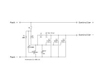
eBike Master Switch Design

Pricing depends so much on how they are sold. It could range from a bare board or kit up to a packaged and tested product with cables and connectors. It is designed to be low cost, no machining, no blocks of copper, etc. Let's see how it plays out, whether we have to make major changes, etc. The major hardware costs are the FETs and the PC board, so you can estimate that and multiply by 2-5 for a rough guess.
 
No smoke here, haven't assembled mine yet either. Fell off a 1 meter platform to my ribs, I need a few extra days rest now :x Top of the list though, should be able to do it by the weekend.
 
As I remember methods tested his boards by turning them on and off with a 100A/100V power supply running through them. Obviously the intent was a little different, but it may be a good benchmark down the road.
 
If the soft-time was 1 second and it was a resistive load (10KW) that would put 5,000 watt-seconds into the FETs, which is about the amount of energy required to heat a liter of water one centigrade degree. It would raise the temperature of the board and FETs a lot more than one degree, and if you want it to stay cool you'll have to add a mass of aluminum or copper. But this has little to do with normal use, and it can be added by the user if they feel a need for it.

My main concern is that the heating from the current is managed, and that the boards work properly and are not fragile. Then we can explore the more extreme testing you suggest. :)
 
very very nice boards Alan :)

how much peak and continuos current can they manage?

are there any plans for boards with more FET's ore other sizes (i think TO-247 would be fine for very high powered bikes)
 
madin88 said:
... how much peak and continuos current can they manage? ...
we will see. atm i'm building one version with 2 4110 fets to see how warm they become running a 4.5kW bike. my setup is similar to your's. almost the same voltage but lower amps. so if 2 fets can handle 4.5kW, 4 fets will easily handle your bike's demand.
with my other switch (same circit, different design) those fets don't get even warm. so i'm quite confident that this should work with to-220 fets as well.
 
dmwahl said:
As I remember methods tested his boards by turning them on and off with a 100A/100V power supply running through them. Obviously the intent was a little different, but it may be a good benchmark down the road.

I think that was for dropping the load quickly. If you want to tie in a LVC to the switch, it would be good if the FETs turn off quickly to avoid anything like 5000 Watt seconds (instant plasma).
 
@ izeman:

so 4,5kw means about 50A batt on "our" voltage :) ?
yes please keep us informed if 2 FET's can hadle this

fechter said:
I think that was for dropping the load quickly. If you want to tie in a LVC to the switch, it would be good if the FETs turn off quickly to avoid anything like 5000 Watt seconds (instant plasma).

My keyswitch connects gate to ground in off position as it is suggested in te circuit.
Will i have a problem if i turn off under load? For example something is going wrong during riding and i use my keyswitch like a kill switch to cut the power.
 
If you ground the gates it will turn off very fast. Not sure about inductive kickbacks, they might cause problems.

If we set the soft-time to 100mS then we will only see about 500 watt seconds which is not much. (Which is about where we are)

If there is a simple circuit to speed turn-off I will definitely consider it. I've looked at it a little but didn't see a good simple solution, though I didn't look very hard.

With our present values of 100K and 1uF the time constant is 100mS so it is not all that slow.

Let's try some math:

Charging Cycle:

(Vin-Vt)/R1 = C1 * dV/dT (for closed switch, assuming R2 is not small compared to R1)

Discharging Cycle:

Vt/R2 = C1 * dV/dT (for open switch) (shorted to ground switch would be faster due to parallel R1, R2)

So discharging is slower than charging by the ratio:

((Vin-Vt)/R1) / (Vt/R2)

So for Vt of 3 volts and Vin of 100 volts, R1,2 of 100K discharging is 33 times slower than charging.

And for C1 of 1uF the dV/dT for turning on is 970 volts/second, so about 100mS. (Actually compensating for R2 this is 940 volts/second or 106mS instead of 103mS at 100V)

Turning off would be about 3.5 seconds. However if the controller logic power is wired as recommended the controller will shut down as soon as the kill switch is opened and the logic supply drains down, (which is the normal situation on ebikes that have main power connected to the controller full time), so the 3.4 second turn off will apply only to the auxiliary loads.

On my Greyborg presently the kill switch only shuts down controller power, main power is controlled by large connectors that are not normally removed, so adding the Master Switch will not change the controller shutdown, it will just also shut down the main power shortly afterward. Without the Master Switch the mains power would not be shut down. In both cases the controller power is shut off immediately by the kill switch.

Note that on lower voltage ebikes the ratio is reduced, so turn-off is more like 1 second on 36V, 1.5 seconds on 48V and 2 seconds on 75V (with 100K/100K R1/R2 values).

This can be improved by reducing R2 which might be worthwhile. A circuit that detects removal of the control input and shorts out the FET gates would speed this further, but interrupting large currents quickly will produce huge voltage spikes that could cause damage as well, so it is a tradeoff. :)

Let's see what reducing R2 can do:

If we make R2 10% of R1, or 10K when R1 is 100K the turn-off will be 10X faster, or 3.2 times slower than turn-on. Turn-on will be slightly slower due to reduction of R2, so turn-on will be increased to about 150mS and turn-off will be about 500mS in the 100V ebike.

So perhaps using 100K/10K for R1/R2 is a good compromise? Controller logic power goes off immediately, and mains power goes off half a second later?

Note that at lower ebike voltages this lower value of R2 will slow turn-on and turn-off, so that's why I didn't do it initially. The R1/R2 ratio needs to be tuned for the bike voltages, due to the relationship between the bike voltage and the FET turn-on threshold voltage.
 
Below is an example of a way to get a faster turn off with a two wire switch.
The transistor is held off when the circuit is on. When the switch is turned off, the base of the transistor gets pulled down and drains the gate. The transistor would only see 12v. A high gain version would be faster.

There is another version that uses two transistors in a SCR like configuration. I like simple though.

I have not tested this. It would be easy enough to set up and measure with an oscilloscope to see how fast it can turn off. Since the controller usually has large capacitors across the power input, the FETs don't need to turn off super fast since the caps will hold up the load while the FETs are turning off, keeping the heat off them.

Automatic Precharge 2 wire with fast off.jpg
 
OK, here are some calculations that hopefully are correct for turn-on, off, for various voltages and R2 values. If we want to get turn-off below about 3 times the turn-on value we will have to add extra circuitry as Richard suggests. Of course this is dependent on testing validating these calculations. note that Vgate is a check to insure that the gates turn on, if R2 is too small they won't ever turn on (or they'll turn partially on and fry the FETs). The Vgate value is the final value after turn-on, and should be sufficient to fully saturate the FET. I used 8+ volts as a rule of thumb for selecting values of R2 and chose standard 10% values.

So how do folks feel about under 1/3 of a second turn-off versus "faster" and adding a few parts (two semiconductors)?
 
Hi Richard, was thinking about different configurations and worrying about protecting the base of that PNP transistor from external spikes.

Came up with this which would seem to protect the transistor from the environment a bit, any comments?

Ebike%2520Master%2520Switch%2520PCB%2520Schematic%2520I%2520c.png


R1 and R2 can both be the same value, say 100K for Vbattery above 18V or so. Q5 must have a lower threshold turn on voltage than the main power FETs.

Using a low voltage zener for D2 would provide some additional protection for Q5's gate, or another diode gate to ground on Q5 to protect against negative impulses.
 
Alan B said:
If you ground the gates it will turn off very fast. Not sure about inductive kickbacks, they might cause problems.

yes this is what i plan to do. Nothing other complicated things :)

I have a 3-wire Keyswitch:

ON position: wire to Masterswitch is connected to positive source in which R = 1M installed
OFF position: wire to Master switch is connected to ground source WITHOUT any resistor

turn off time sould be instant or i am wrong?
if there are inductive kickbacks, would it help to also add a resistor in the ground source wire?

Sorry but its a bit confusing because in the "Active pre-charge/inrush control" thread the circuit pics look different (2-wire vs 3-wire switch is the reason i think).

another question:

in my box with the circuit i have installed on controller side about 2000µF capacitors (to prevent controller from big spikes). Will i get some problems with precharging this big capacity?
With "R2" 1M it sould not be 100ms but rather 1sec right?
 
1 meg and 1 pF make time constant of one second. I think that is too long and it makes it more likely that other loads could come online before the soft turn on is complete.

Ramping on softly prevents spikes, the 2000uF is probably not helping. Controllers need low ESR capacitance really close to the FETs, large caps far away can't contribute much.

Turning off fast creates spikes that probably go into the body diodes of the Master Switch FETs.

Adding gate resistance to slow down switching doesn't slow it very much.

Adding source resistance on the switching FETs would waste a LOT of power and is probably not what you meant.

Note that when turning on the current balance between the FETs is not going to be great. It would be nice to match the FETs for gate transition voltage to reduce this problem, but it is a lot of work and requires a lot of FETs to choose from. So turning on with a significant load is not going to evenly heat the FETs (unless you have matched them). Turning off is more even as the essentially equal diode threshold losses inherently help to balance current.

Also note that turning off the kill switch when you are crashing is rare, unless you build an automatic detection circuit most of the time it is not going to be turned off. Plus ergonomic standard kill switches are SPST, not SPDT, at least the several I have purchased. Using some other non-ergonomic switch is going to make it even less likely that it will be turned off in a problem event.

I just re-read and see you mean an ignition switch, not a kill switch. I think every ebike should have a kill switch. Something right under your thumb. Many accidents occur because the bike is turned on and being moved around and the throttle gets bumped. It should be easy to enable/disable the bike while pushing it, etc. The key switch and the kill switch are separate items. The kill switch can go to the controller logic power.
 
If you suddenly turn off the FETs under full load, the capacitors in the controller will hold up the load long enough to prevent huge voltage spikes. There will still be some from the inductance in the wiring, so good to have some headroom in the voltage rating. Grounding the gates will make the FETs turn off as fast as possible.

Something like a big TVS diode across the FET drain-source might be good if you're running close to the voltage rating.

If the FETs try to turn off slowly under full load, I can almost guarantee destruction. This shouldn't happen normally but would be an issue if you were interfaced to a LVC on the batteries or if you had a blown controller feeding a brushed motor.

During precharge, a single FET is enough to charge the capacitors if done at the right speed. As I recall, 100V over 1 second into 10,000uF works out to 1A. Once it's past precharge, they should all be fully on. Any differences in turn-on time won't matter. Once all fully on, current sharing will depend on path resistance more than anything, so board layout should try to keep the path resistances equal.
 
Alan B said:
Ramping on softly prevents spikes, the 2000uF is probably not helping. Controllers need low ESR capacitance really close to the FETs, large caps far away can't contribute much.

Yes i know. The wire from the caps to my Max-E controller is about 20cm long and is big 6mm². It should help a little to reduce voltage spikes at high phase current (Adaptto asserts this is good if you run the controller close to the voltage rating).
Adding source resistance on the switching FETs would waste a LOT of power and is probably not what you meant.

I mean if i should add a resistor in the wire of my keyswitch which short gate to ground. Now i think this is not a good idea because its better to turn off as fast as possible.

fechter said:
During precharge, a single FET is enough to charge the capacitors if done at the right speed. As I recall, 100V over 1 second into 10,000uF works out to 1A. Once it's past precharge, they should all be fully on. Any differences in turn-on time won't matter. Once all fully on, current sharing will depend on path resistance more than anything, so board layout should try to keep the path resistances equal.

OK, thx for your explanation
 
Alan B said:
No reports of smoke yet, I guess that's good. :?:
I got delayed on ordering parts, but they arrived yesterday afternoon, so I'll see about assembling it this weekend. Since I don't plan to go over 14s I ordered the NXP PSMN5R0-80PS,127 FETs for the low on resistance and low price.

I was not following the resistor value vs turn on/off time discussion completely, but I have plenty of resistors. What is the current best advice for resistor values for a 48 to 60 volt system?
 
i finished assembling the switch now, and got first results. i installed 2 4110 fets and resistors as mentioned in alan's thread on page1.
bike is 80v and 4500w. so this gives good 50a load.

when i connect the switch to the battery only, and DO NOT connect positive wire from the battery to anything, i get a small flash when connecting the controller then. a small flash, but still a flash. also if i measure voltage from the switch output BEFORE powering it on, there is full voltage on the output, slowly dropping to zero. dropping takes some minutes. about 3 seconds from 80v to 20v, and some 3 minutes from 20v to almost zero.

turning the switch on raised voltage from 0V to 80V almost immediately - for sure under a second. my voltmeter was not able to update the display that fast.

i then tested heating of the fets. 1min fully load (4.5kw) going uphill didn't warm that at all. ambient temp was around 8°C, so quite cold, but the switch was in the battery box and no air flow. still temperature immediately after the test run was 22°C. so i guess you could run MUCH more current if you install 4x 4110. the result is equal to my other switch - no heating at all with 4x 4110.

so if you experience some heat you could still screw some metal bar over all for metal parts of the fets as a heat spreader. this would help. but it may not be needed.

open to questions :)
 
Alan B said:
Nice on heating!

Need to understand the flash situation bettter.

Ramp at on is 0.1 sec.

0.1s seems reasonable. it's almost instant on. which is fine, and the fets don't have a problem with it.
this flash thing is REALLY weird, as there is no supply voltage to be seen. the positive wire is ONLY needed to supply gate voltage. and is ONLY connected to the circuit when you switch it on. but somehow the fets seem to turn on by applying GND only. NO IDEA HOW. it's only a short period of time, but enough to close the connection betwee B- and C-.
 
Back
Top