Efficiency, noise, sinusoidal, trapezoid....

hejo

1 W
Joined
Sep 26, 2007
Messages
50
Location
Germany
Hi experts, after studying lots of posts here i am a little confused und hope to get some enlightening help from you :

my equipment :

5303 with 40A controller
408 with 20A controller
GL-1 with "comfort" controller from a German supplier

Since i have two trikes i had the chance to test all motors in direct comparison in terms of torque, accelleration, efficiency , range etc.

( i must add that my main objective was to operate the drives in the speed and current range giving highest possible efiiciency and lowest possible noise by using my 14 gear hub).

My findings are somehow surprising :

the GL-1 is by far the most efficient drive, but terribly noisy (it it somehow a sharp ringing noise) operated at 9 Amps full throttle constantly on a 3% inclination test distance my CA shows 1.8 Ah drawn from battery (Li 40V).

next is the 408 motor
it is the quitest motor and is performing the test distance consuming 2.3 Ah (same torque, same speed)

from the spec sheets provided at Crystalyte i expected from the 5303 an even higher efficiency, but the 5303 is slightly more noisy and draws 2.9 Ah from the battery.

I tried to operate the 5303 at 15A and 20A expecting some better efficiency, but it got worse to 3.2 Ah at 260 rpm of the motor and 3.6 Ah (double the consumption of the GL-1) at 340 rpm of the motor.


I have read :

Lowell : My X503 is much louder than the X5304, which is to say the X5304 is virtually silent, whereas the X503 is audible at certain speeds.

The7 : Motors of case 2 (GL2, BMC/Puma) usually have smooth drag and their back emf are (nearly) sinusoidal. In general they have a less average drag and a bit quietr in running.


I have ordered a Brushless controller evaluation kit from ST- and want to test the different motors with sinusoidal feed. http://www.st.com/stonline/products/literature/an/12375.pdf

Question is :

Is highest efficiency really linked to increased noise?
How is the 408 / 5303 are performing beeing fed with sinusoidal PWM?

What are your experiences
 
Not as Hard as Quantum Physics (but close)

Since you have 14 gears to choose from it's possible for you to be running different gears on those hills for those motors. The problem is going to have to do with the powerband shape of each motor. Every motor will have a slightly different no load speed and that has a proportional relationship with peak efficiency rpm. So the real problem with your testing methodology is that unless you could calculate the peak efficiency rpm in advance and then gear your motors (differently) so they CLIMB at the exact same speed you would not be getting a fair test.

:arrow: A hill and a speed demand a certain amount of work.

:arrow: If you increase the speed the work demand increases.

:arrow: If you lower the gearing then a motor can climb the same hill with the same weight with LESS energy because you are doing less work and climbing at a slower speed.

Even if you repeat the test and make sure that you are going up the hill at the same speed you don't know for each motor if that's a "preferred speed" for that motor. What you have is differing "quantum levels" where in each gear for each motor there is a "sweet spot". Trying to run 10 mph might be in the middle of the "sweet spot" for one motor, but the other might prefer 11 mph or 9 mph depending on it's maximum rpm.

:arrow: Hopefully you see how really hard it is to test things this way.

You are better off using some sort of dyno to test the motor output directly because the gears can produce results that are hard to analyze.
 
Hi safe

My motor spec (i believe it is a BL-1) is attached.
Ther date for the crystalyte motors are known.
My reading is that if i operate between 3 to 9 A i should have an efficiency above 80%, provided I maintain a motorspeed around 60-80% of unloaded speed.
This is what i tested.

My understanding is :
Power = torque x speed
If my vehicle is 130 kg, the inclination is 10m within 100m (10%) i have to pull 13 kg to get the vehicle moving (at low speeds the rolling friction is indeed neglegable).
With my 20" wheel the equivalent of 13 kg pulling is approx 33Nm torque at the driving axis.
Going at 1,94 m/sec. = 7km/h would require 248 Watt
With my battery fully charged (41V) dropping to 40V at around 7A
actual test shows 7A at around 250 rpm of the motor pulls my vehicle at 7 km/h.
Amazingly 7A x 40V = 280W power in, should result in approx 235 W power out (minus losses in chain and gear system), but still this moves my vehicle at exactly 7 km/h (measured with CA and GPS ...

:wink:

Possibly my spring operated measuring device for pulling is not really good....

If i use the 408 motor i choose an amp range around 9-10A and a motor rpm range between 220-25o rpm,, with the 5303 an amp range around 10-12A, motor rpm 300-330 expecting the highest efficiency.

But the results are poor compared with the BL1.
In all cases i choosed the gears to achive the above figures.
(btw : it gets worse if i choose higher or lower speeds / Amps)
 
A hill and a speed demand a certain amount of work.

If you increase the speed the work demand increases.

If you lower the gearing then a motor can climb the same hill with the same weight with LESS energy because you are doing less work and climbing at a slower speed.

I i have a certain distance ahead of me ( example 4 km with 200m gain in altitude)
And i have two identical vehicles, identical battery, identically set CA and, no matter which gear, speed, throttle i choose, at the end i measure 1.6 Ah with one drive system and 3.1 Ah with the other drive, i still do not care what dynamometers are trying to tell me, but for me the first drive is more efficient than the other.

climbing a hill at a speed of 2km/h or a speed of 10km/h (at such low speeds the losses due to air resistance are still neglegable) requires the same amount of energy!
Power is not the same as work/energy, at least thats what i learned in school...
 
Sorry, i forgot to attach my motor data
 

Attachments

  • Motordaten 250W-36V.pdf
    25.4 KB · Views: 110
That's very interesting.

Since the energy needed to create noise is wasted, it seems like the most efficient state should also be the quietest.

A mismatch between the drive waveform and the BEMF waveform is not going to make much difference in efficiency (at least between trapezoidal vs. sine wave).

I'd love to see how an Xlyte motor performs with a sine wave drive.

From the ST evaluation kit document:
Appendix A
Phase current comparison between 6 step BLDC drive and sine BLDC drive for same power output

For same power output, average DC link current is same
6 Step BLDC motor phase currents:
Iav = 2. Id /3 Irms(BLDC) = sqrt(2/3).Id = 0.8165 . Id
Sine-drive motor phase currents:
Iav= 2. Im / π Where, Im = (π/3). Id → under same power delivery Irms(SINE)= [π / (3.sqrt(2))] . Id = 0.74 . Id Irms(SINE) / Irms(BLDC) = 0.906
This shows that with a sine-drive BLDC approach, the phase rms current is lower by nearly 10% compared to a 6 step
 
fechter said:
For same power output, average DC link current is same
6 Step BLDC motor phase currents:
Iav = 2. Id /3 Irms(BLDC) = sqrt(2/3).Id = 0.8165 . Id
Sine-drive motor phase currents:
Iav= 2. Im / π Where, Im = (π/3). Id → under same power delivery Irms(SINE)= [π / (3.sqrt(2))] . Id = 0.74 . Id Irms(SINE) / Irms(BLDC) = 0.906
This shows that with a sine-drive BLDC approach, the phase rms current is lower by nearly 10% compared to a 6 step

I wonder if you could "sell" that benefit as a way to offset the additional cost of a true sine controller.

:?
 
I see a couple problems in your measuring that may be effecting the results.

1. you're measuring the motors in Amp Draw. because of the diffrences in the motors, they will have diffrent rates of voltage sag at the same speeds, and that will change your amperage readings.
Power is measured in Watts. Your data will be more accurate measured in Watts, for comparing the efficancies of the motors. amps X volts = watts

2. the C-lyte motors both run more efficently at higher voltage levels. You didn't state the test voltage, and I don't know the efficancy of the GL-1 motor, but generaly the C-lytes prefer voltage over 48V. The higher the voltage, the lower the amperage for the same wattage at the same speed, but that wattage will decrease as the efficancy goes up.


As for sound, it takes a good deal of wattage to make sound, and generaly anything that is making sound as a waste product is also making heat as a waste product. If 60 db sound at 1 meter takes 3 watts, and if it's the product of gears meshing, its probably producing atleast 3 watts of heat. every 3 DB of sound doubles the power usage.
 
You've basically ignored my basic point which is that when you use gears there are "quantum levels" for each gear. Within the gear there are better and worse situations to be in as far as efficiency.

You seem to be focused on the peak efficiency current which is basically going to be tied to the no load current of the motor.

:arrow: Things are more complicated than this however...

But... since you use 14 gears... it's not that far off from what is valid. If you can select the right gear all the time and stay within your peak efficiency all the time then you can get some really impressive overall efficiency.

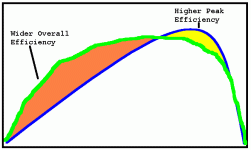
This chart isn't that great, but it expresses the idea. You might have a motor that has an overall efficiency that isn't that great (because it's running a high current limit controller for example) but since the other motor has a narrow peak that is good (and you have gears) you can achieve better results with the "worse" motor. :shock:

:arrow: Gears allow you to get the most out of the motor... so maybe your technique is good in that you are testing for what you WANT to get... (rather than objectively testing the motors powerbands)

I usually test for the opposite performance which is the "peak power" and that changes the way you evaluate things. I'm into the "sport" aspect of motor power and eventually I'm hoping to switch to an induction motor like the Tesla roadster uses. (one day far, far away)
 

Attachments

  • different gears and motors 02.gif
    different gears and motors 02.gif
    7.1 KB · Views: 2,299
Drunkskunk said:
I see a couple problems in your measuring that may be effecting the results.

1. you're measuring the motors in Amp Draw. because of the diffrences in the motors, they will have diffrent rates of voltage sag at the same speeds, and that will change your amperage readings.
Power is measured in Watts. Your data will be more accurate measured in Watts, for comparing the efficancies of the motors. amps X volts = watts

At low level currents low differences on voltage sag is a minor problem.

Drunkskunk said:
2. the C-lyte motors both run more efficently at higher voltage levels. You didn't state the test voltage, and I don't know the efficancy of the GL-1 motor, but generaly the C-lytes prefer voltage over 48V. The higher the voltage, the lower the amperage for the same wattage at the same speed, but that wattage will decrease as the efficancy goes up.

C-lyte motors are inefficient at low rpms ( low to medium currents) this is the real problem.

hejo do the systematic error - he skip over the friction resistance.
At higher speed ( higher rpm) C-lyte is the same efficient as his GL-1 but at the same case friction resistance need more watts of course.
So if he assume the friction resistance is negligible than he calculate wrong (too low ) efficiency for C-lyte at higher speed.
All friction wattage (and air drag wattage too) goes to the motor waste side in his wrong calculations.
This is the systematic error.

Drunkskunk said:
As for sound, it takes a good deal of wattage to make sound, and generaly anything that is making sound as a waste product is also making heat as a waste product. If 60 db sound at 1 meter takes 3 watts, and if it's the product of gears meshing, its probably producing atleast 3 watts of heat. every 3 DB of sound doubles the power usage.

It is true but it is again minor problem.

Regards
 
Fechter :
i should have the ST MC Kit within a couple of days and looking forward to drive the Crystalyte and the GL-1 motor withit to see what happens.
Since i am hoping to switch between different modes there should be a direct comparison be possible.

TD : if you could combine the functionality of a CA with a small digitally motorcontroller and possibly cheap powerboard with an tft display and a bike cumputer ... lets assume you use a no name pocket pc and get Mp3 player, GPS, CA and programmable BL controller alltogether, i have doubts which solution would be more costly...

Drunkskunk and safe : an annoying ringing sound , even if it is 3 watts, would not be the problem, but if i use my two trikes individually, and if my wife consumes 6 Ah with this small BL-1 motor and if my CA shows 14Ah cruising at the same speed using my 5303 choosing gears all the time, trying my best to match the ideal "powerband" / Amps, speed throttle etc. i dont care about all the theory , matter of fact is, that my battery is nearly empty (32V) and my wife´s battery (38V) is still capable to go the same distance again.
There is the main difference.
Safe : you promoted heavily the use of gears. This is, what i do, all the time.
And since my wife does not care too much calculating efficiency, Amps and Voltages, just giving throttle as she enjoys cruising.... whereas I have spent many days and trips to find out why my motor (408 or 5303) is draining the battery more empty.
And unfortunately with the 5303 we are not talking about a few percent, there if often 100% difference!
I should mention that my wifes very good consumption data are obtained only in "economy mode" that means the controller is current limited to 250 Watts (sometimes 6A, sometimes 14A), dont ask me how this controller is set / programmed to do this.
 
eP : i was talking about the rolling resistance (elastic deformation of tyre on a given road) which should not be too important if i compare low speed (6km/h versus 12 km/h) at such speeds even air resistancs / drag should not have major influence... and once again : if we use identical trikes (my weight is just 7 kg more than my wife´s) and if we go for a tour, no matter if i try to at high motor speed (280-350 rpm) or low speed by using my 14 gears, the result is dramatic.
I am going to continue testing.
If my thoughts are wrong, any advice for better testing methods using two identical vehicles driving together .... are highly appreciated
 
hejo said:
FechAnd since my wife does not care too much calculating efficiency, Amps and Voltages, just giving throttle as she enjoys cruising.... whereas I have spent many days and trips to find out why my motor (408 or 5303) is draining the battery more empty.


First of all I'm sure your wife weighs less than you. (so that's one area of difference)

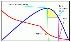
Second, sometimes riding based on "feel" does a better job than if you ride based on some artificial idea about what you want to do. (like staring at an ammeter) If you are constantly seeking the LOWEST amps that doesn't necessarily mean that you are at peak efficiency. The amps keep going down and down and down all the way until you hit your no load speed. But while the amps go down the efficiency is also going down.

:arrow: Blue line is efficiency.

:arrow: Red line is current.

You would be better to CALCULATE the peak efficiency current and try to stay exactly at that level while riding rather than seek lowest amps which isn't that good as far as efficiency...
 

Attachments

  • different gears and motors 03.gif
    different gears and motors 03.gif
    8.2 KB · Views: 2,265
Common Misconception

:arrow: The lowest current does NOT produce the highest efficiency for a permanent magnet motor.
 
Going by the motor data you posted you should NEVER go above or below 5-7 amps. To allow the rpms to rise above 280 rpm will just start to make you lose efficiency as will below 250 rpm. (but there is more power below 250 rpm... a nasty temptation that produces heat lowering efficiency... it's better to downshift)
 
From the ST evaluation kit document:
Appendix A
Phase current comparison between 6 step BLDC drive and sine BLDC drive for same power output

For same power output, average DC link current is same
6 Step BLDC motor phase currents:
Iav = 2. Id /3 Irms(BLDC) = sqrt(2/3).Id = 0.8165 . Id
Sine-drive motor phase currents:
Iav= 2. Im / π Where, Im = (π/3). Id → under same power delivery Irms(SINE)= [π / (3.sqrt(2))] . Id = 0.74 . Id Irms(SINE) / Irms(BLDC) = 0.906

Seems that "For same power output, average DC link current is same 6 Step BLDC motor phase currents" is not an valid assumption.


The exact analysis should resolve the 6-step waveform into the fundamental and harmonic components.

6-STEP drive has the fundamental and harmonic components.
SINE drive has only the fundamental component.
Only the fundamental component will give the forward output torque (or output power).
This shows the SINE drive is more effective than 6-STEP drive.

But SINE drive is more complicate and has more switching loss in controller than 6-STEP drive.
Overall SINE drive is still slightly more efficiency and quieter.
 
hejo said:
eP : i was talking about the rolling resistance (elastic deformation of tyre on a given road) which should not be too important if i compare low speed (6km/h versus 12 km/h) at such speeds even air resistancs / drag should not have major influence... and once again : if we use identical trikes (my weight is just 7 kg more than my wife´s) and if we go for a tour, no matter if i try to at high motor speed (280-350 rpm) or low speed by using my 14 gears, the result is dramatic.
I am going to continue testing.
If my thoughts are wrong, any advice for better testing methods using two identical vehicles driving together .... are highly appreciated

I've read again what you wrote and i'm not sure what you claim.
GL-1 drain 1.8Ah at 9A rate so the trip time is 12 minutes.
5303 at 20A drain 3.6 Ah, so trip time is 10m48s .

Are you sure the 5303 voltage is also 40 volts ?
What is the idle current at 350 rpm for your 5303 ?

Maybe your motor fail (magnets overheated or something else )?
 
The7 said:
But SINE drive is more complicate and has more switching loss in controller than 6-STEP drive.
Overall SINE drive is still slightly more efficiency and quieter.

I would recommend checking out Don Lancaster's "magic sines" technique of synthesizing sine waves with slow-switching square waves. It gets you most of the benefits of true sine wave power without high switching frequencies.

http://www.tinaja.com/magsn01.asp
 
The paper states that they have these limitations:
• The first pair of uncontrolled odd
harmonics are often fairly strong
and may even be comparable in
strength to the fundamental.
• Lowpass filtering may be needed,
provided by motor inductance and
the load interia.
• Highly precise timing is required,
to 1 part in 30,000 or better.
• Speed or frequency may have to
be set by a second PLL circuit.
• Best suited for power and lower
audio frequencies.
• Reasonably wide speed/frequency
range does not go down to dc.

And also they seem good for fixed frequency appliaction and not for variable speed drive.
 
hejo, The "GL-1" hub motor has different size wire & # of windings according to "bigpond.com" but similar characteristics otherwise. They also said they get much better rage from the GL1 motor@ 48volts when tested against the 408/with 48v.

noise... the annoying ringing sound might be some resonant frequency accumulated from somewhere and is buzzing against the cover of the motor, which is curiusly shaped like a bell. Just something to check that hasn't been mentioned yet. Good luck with your project, love those Hase trikes, I want one, anything i should know before ordering?
 
Back
Top