Hi All,
What:
I've got a project that has been lingering around for a couple of years now and due to many personal moves and readjustments I never really had a chance to finish it. However, now I'm ready to start it back up and finish it for good. To make a long story short I originally intended it to be a street bike mainly, but after moving to Europe and learning that it is very difficult and expensive to register a custom electric motorcycle for street use I decided to make it a track only bike. It kind of works out better in the end and will be more fun because I can do more custom things!
Who:
A bit of background about me. I'm a Mechanical Engineer working in the motorcycle industry. Motorcycles are awesome! Electric ones even more so! I'm from Chicago, but now I'm in Europe (Austria). I have a solid understanding of EVs and electronics, but I'm hoping to learn some helpful things along the way here. I've been lurking on ES forum for quit some time so I decided to share my build.
Goal:
I want to use this thread to share my build progress, get some advice on certain things, and hopefully meet some local EV enthusiast. As far as the bike goes I want to start out with some track days to check out the overall performance in the Summer of 2019 and then if all goes well maybe some amateur racing. I have some future plans for liquid cooling after the build is completed and the weaknesses are identified.
I already have most of major components that I had planned to use a couple of years ago when this thing was supposed to be a street bike. So there's no turning back at this point. I do believe that I can build a decent track bike with what I have as long as I keep the overall weight down ~ 370 lbs, ensure proper gearing, hopefully do some performance tuning (dual Sevcons ??), and of course keeping the electrons flowing :lol: aka thermal management. Anyway here is some more info and pictures. More to follow.
Bike:
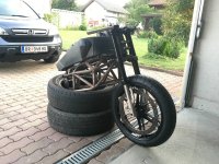
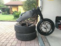
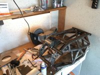
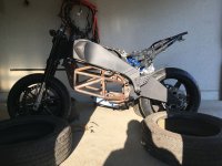
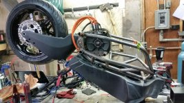
Donor chassis: 2004 Buell xb12r + a custom steel tube "sub-frame" to support all the electronic bits and the swing arm as well. Since the original Buell XB chassis uses the engine as a stressed member I needed a way to bridge the gap to the swing arm.
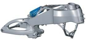
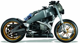
So this is what I came up with. The pink part is simply where the OEM exhaust should end up for visual reference of the ground clearance.
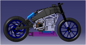
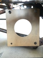
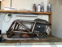
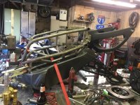
The steel tube frame is made from mild steel 1020 DOM 1" OD tubing with 3/4" OD tubing for the support members. The motor mounts are made from 2D laser cut steel plates and welded to supporting points on the frame.
View attachment 4
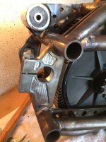
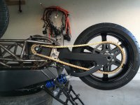
The swing arm mounts are 2D machined also out of mild steel and welded to the frame at the rear. The whole thing is a tad over designed but because it's connecting the frame to the swing arm and holding mass I wanted to be sure it would have enough strength and retain or improve the entire vehicle stiffness. I think I may have actually increased it. The total weight of the welded "sub-frame" is ~40 lbs.
View attachment 3
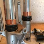
Suspension: Stock Showa fork and shock for now, but plan to upgrade eventually and maybe even swap the entire front end for some dual rotors and Brembo brakes.
Aero: Plan to get a full race fairing.
Now for the EV part of it..
Motor: 2014 ZF75-7R with higher temp magnets (SPM)
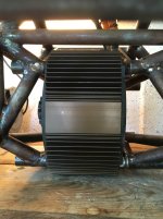
Controller: Sevcon Gen4 Size 6 72-80V Nominal
Batteries: 2012 style Nissan Leaf modules x 14 so ~6 kWh @ nominal voltage. I don't plan on building a "battery box", since this will be for racing only, unless I need to go with liquid cooling. I will still make some kind of debris shield out of CF or Fiberglass.
Charger: TBD will be off-board for sure (thinking power supplies in series and parallel I want to build a 7-10 kW charger) If my logic is correct with a 10 kW charger I could recharge in about 40 min (which is the time between track day session) if I charge at 1C-1.5C at the cost of reduce cycle life. Also I would probably need to keep the cell temp. down in order to charge at those C-rates so maybe some liquid cooling or advanced air cooling will be necessary? What do you guys think?
BMS: TBD not sure yet if I will use one. I know the Sevcon can do LV protection but I'd be worried about the over charging.
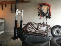
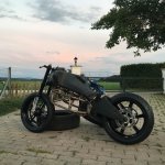
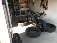
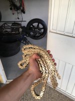
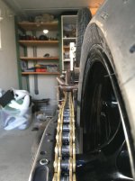
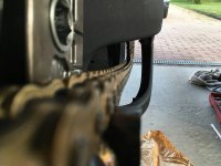
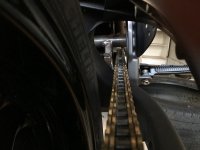
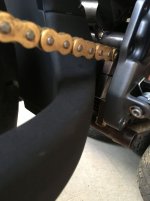
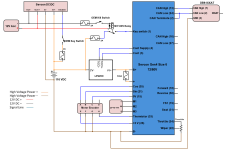
At the moment I am assembling most of the mechanical parts of the bike together to get a rolling chassis. The motor mounting is already part of the welded steel tube "sub-frame", the batteries have been packaged for the most part but I need to weld on a few brackets to hold them. The controller needs to be mounted (either under the seat or under the batteries). After that will follow a few more mechanical things such as a chain tensioner since the Buell swing arm does not have adjusting screws at the end, some kind of 3D printed enclosure box for the main contractor and other electrical bits, and BMS if I will end up using one. Then I will start working on the wiring harness and battery connections and finally the setup up of the ZF75-7 and the Sevcon using the DVT software. Like I said the goal is summer 2019 first track day. First test ride early 2019.
View attachment 2
I think that's a good start for now. I hope you enjoy my build. I'm looking forward to your comments and criticisms . You can follow me on Instagram @ stamen.tintikov if you want. I will also post photos and videos of the build there. Stay tuned...
What:
I've got a project that has been lingering around for a couple of years now and due to many personal moves and readjustments I never really had a chance to finish it. However, now I'm ready to start it back up and finish it for good. To make a long story short I originally intended it to be a street bike mainly, but after moving to Europe and learning that it is very difficult and expensive to register a custom electric motorcycle for street use I decided to make it a track only bike. It kind of works out better in the end and will be more fun because I can do more custom things!
Who:
A bit of background about me. I'm a Mechanical Engineer working in the motorcycle industry. Motorcycles are awesome! Electric ones even more so!
Goal:
I want to use this thread to share my build progress, get some advice on certain things, and hopefully meet some local EV enthusiast. As far as the bike goes I want to start out with some track days to check out the overall performance in the Summer of 2019 and then if all goes well maybe some amateur racing. I have some future plans for liquid cooling after the build is completed and the weaknesses are identified.
I already have most of major components that I had planned to use a couple of years ago when this thing was supposed to be a street bike. So there's no turning back at this point. I do believe that I can build a decent track bike with what I have as long as I keep the overall weight down ~ 370 lbs, ensure proper gearing, hopefully do some performance tuning (dual Sevcons ??), and of course keeping the electrons flowing :lol: aka thermal management. Anyway here is some more info and pictures. More to follow.
Bike:
Donor chassis: 2004 Buell xb12r + a custom steel tube "sub-frame" to support all the electronic bits and the swing arm as well. Since the original Buell XB chassis uses the engine as a stressed member I needed a way to bridge the gap to the swing arm.


So this is what I came up with. The pink part is simply where the OEM exhaust should end up for visual reference of the ground clearance.

The steel tube frame is made from mild steel 1020 DOM 1" OD tubing with 3/4" OD tubing for the support members. The motor mounts are made from 2D laser cut steel plates and welded to supporting points on the frame.
View attachment 4
The swing arm mounts are 2D machined also out of mild steel and welded to the frame at the rear. The whole thing is a tad over designed but because it's connecting the frame to the swing arm and holding mass I wanted to be sure it would have enough strength and retain or improve the entire vehicle stiffness. I think I may have actually increased it. The total weight of the welded "sub-frame" is ~40 lbs.
View attachment 3
Suspension: Stock Showa fork and shock for now, but plan to upgrade eventually and maybe even swap the entire front end for some dual rotors and Brembo brakes.
Aero: Plan to get a full race fairing.
Now for the EV part of it..
Motor: 2014 ZF75-7R with higher temp magnets (SPM)
Controller: Sevcon Gen4 Size 6 72-80V Nominal
Batteries: 2012 style Nissan Leaf modules x 14 so ~6 kWh @ nominal voltage. I don't plan on building a "battery box", since this will be for racing only, unless I need to go with liquid cooling. I will still make some kind of debris shield out of CF or Fiberglass.
Charger: TBD will be off-board for sure (thinking power supplies in series and parallel I want to build a 7-10 kW charger) If my logic is correct with a 10 kW charger I could recharge in about 40 min (which is the time between track day session) if I charge at 1C-1.5C at the cost of reduce cycle life. Also I would probably need to keep the cell temp. down in order to charge at those C-rates so maybe some liquid cooling or advanced air cooling will be necessary? What do you guys think?
BMS: TBD not sure yet if I will use one. I know the Sevcon can do LV protection but I'd be worried about the over charging.
At the moment I am assembling most of the mechanical parts of the bike together to get a rolling chassis. The motor mounting is already part of the welded steel tube "sub-frame", the batteries have been packaged for the most part but I need to weld on a few brackets to hold them. The controller needs to be mounted (either under the seat or under the batteries). After that will follow a few more mechanical things such as a chain tensioner since the Buell swing arm does not have adjusting screws at the end, some kind of 3D printed enclosure box for the main contractor and other electrical bits, and BMS if I will end up using one. Then I will start working on the wiring harness and battery connections and finally the setup up of the ZF75-7 and the Sevcon using the DVT software. Like I said the goal is summer 2019 first track day. First test ride early 2019.
View attachment 2


I think that's a good start for now. I hope you enjoy my build. I'm looking forward to your comments and criticisms


