
Hello, new to the space but seems like the right place...
I purchased a ND72680B from ebay seller, I requested sin/cos encoder support and this was the version I was advised to get. Unfortunately the documentation I can find (ebay seller pointed me to facebook group) all shows the wiring of HALL sensor wiring and not how to interface a sin/cos encoder.. My motor has a RMB29AC01SS1 – Analogue sine/cosine encoder.
I've put together a wiring table I've seen two different version of the pinout of the fardriver controllers. Here is what I've come up with:

However I get Encoder Hall error single tone repeats every ~1.5s

Any advice would be greatly appreciated!
Thanks!
Sam
I purchased a ND72680B from ebay seller, I requested sin/cos encoder support and this was the version I was advised to get. Unfortunately the documentation I can find (ebay seller pointed me to facebook group) all shows the wiring of HALL sensor wiring and not how to interface a sin/cos encoder.. My motor has a RMB29AC01SS1 – Analogue sine/cosine encoder.
I've put together a wiring table I've seen two different version of the pinout of the fardriver controllers. Here is what I've come up with:
However I get Encoder Hall error single tone repeats every ~1.5s
Any advice would be greatly appreciated!
Thanks!
Sam
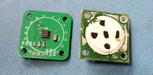

") : 4 poles, 8 magnets. That's 4 pole pairs, since each magnet should be flipped opposite polarity from the next one over.
: 4 poles, 8 magnets. That's 4 pole pairs, since each magnet should be flipped opposite polarity from the next one over. 

