Fechter's Capacitor Coupled Cell Balancer

i was wondering would microwave capacitors and diodes work?

also would motor starter capacitors work for the caps and would the uf ratings all have to be the same?

what about if the power goes out would we have a repeat of the vsx40MD23 flaw where things would smoke?
 
philf said:
So where do we send the coffee grinds and Red Bull?

Sleep deprivation + fechter = inspired ideas...

Great thread.
There's probably another ingredient in there that I can't mention :wink:


Microwave oven caps would be gross overkill.
Even motor starter caps would be huge.
From what I can tell, just little aluminum electrolytics work fine without too much heating. These are a little bigger than a pencil eraser.

I made some progress on parts selections and the cell circuit design.

Now I need a good half bridge circuit to generate the square wave. It would be best if I could find a switching controller chip that would drive both high and low side FETs at 50% duty cycle. There must be something like this, but there are so damn many of those things it takes a long time to search. I can always do it with discrete components.

I want something in a half bridge configuration that can pull up to the 5v (or whatever it takes) and pull down to ground. I only need about 2A, since that's what the bridges are rated at. Efficiency is not a big deal, but I don't want much heat generation.
 
would a 555 timer or the same gate driver used by the bms + some external parts to shape the wave?


also would this work as a charger?


fechter said:
philf said:
So where do we send the coffee grinds and Red Bull?

Sleep deprivation + fechter = inspired ideas...

Great thread.
There's probably another ingredient in there that I can't mention :wink:


Microwave oven caps would be gross overkill.
Even motor starter caps would be huge.
From what I can tell, just little aluminum electrolytics work fine without too much heating. These are a little bigger than a pencil eraser.

I made some progress on parts selections and the cell circuit design.

Now I need a good half bridge circuit to generate the square wave. It would be best if I could find a switching controller chip that would drive both high and low side FETs at 50% duty cycle. There must be something like this, but there are so damn many of those things it takes a long time to search. I can always do it with discrete components.

I want something in a half bridge configuration that can pull up to the 5v (or whatever it takes) and pull down to ground. I only need about 2A, since that's what the bridges are rated at. Efficiency is not a big deal, but I don't want much heat generation.
 
You need some dead time 48/48% duty is safest :) Don't ask me how I know this. :)

There are pleanty of IC's out there that will do what you need. Even a plain old boring SG3525 would do what you want, or a TL494 or... Totem pole drive your mosfets with BD139/140's and robert is your proverbial relation.

I'll see if I can dig up the notes I made when I did this for SLA string charging. Inrush current was handled by using an error amplifier on a shunt which controlled the PWM duty cycle - thats what these IC's are designed to do, no sense in reinventing the wheel.
 
i dont know if this would work but another option is a motor reversal driver.

a motor reversal driver has the delay and and xor logic built in.

a 555 timer could drive an inverter to get a not logic.

then feed the normal logic to the forward pin and the not pin to the reverse pin.

this would work ok for low current maybe less than 1 a.

for higher currents you can build an h bridge using 4 transistors or fets.

good ups's will use some kind of h bridge to make the ac the cheap ups's will use 2 separate windings and switch back and forth between the 2 to get the ac.

the below image is better because it includes an and and inverter circuit for a single wire reversal.


steer-hbridge.jpg

it also includes a pwm pin witch is used for speed control and may not be needed for this unless maybe to vary the charge rate.


if for some reason the image does not show then copy and paste in new window


heathyoung said:
You need some dead time 48/48% duty is safest :) Don't ask me how I know this. :)

There are pleanty of IC's out there that will do what you need. Even a plain old boring SG3525 would do what you want, or a TL494 or... Totem pole drive your mosfets with BD139/140's and robert is your proverbial relation.

I'll see if I can dig up the notes I made when I did this for SLA string charging. Inrush current was handled by using an error amplifier on a shunt which controlled the PWM duty cycle - thats what these IC's are designed to do, no sense in reinventing the wheel.
 
Thanks for the suggestions.

The SG3523 looks like it would work OK, but I was hoping to find something that could drive both FETs directly. The SG3525 looks like it could do that on the low side easy, but would need a bootstrap circuit on the high side. Not too much work. Since my FETs only need to pump around 2A, they can be fairly small. I think the timing would be screwed up if I used a P channel FET on the high side and drove it directly.

I found another interesting one called a BD6212 motor bridge, which has the FETs built in, so pretty much the whole thing is on one part. The problem with it looks like it is fixed at 25khz.

One of my design objectives is always to minimize parts count whenever possible, even if it costs a little more.

In looking at the stated ESR specs for some random "low impedance" electrolytic capacitors, it makes me wonder why the apparently cheap little thing I've been testing with doesn't get hot. I somehow don't trust the datasheets. I'll have to break out the impedance meter at work and actually measure some. Again, I don't need to pump tons of juice through them, but 2A is a good design figure. Some of the datasheet indicated over 1 ohm on caps that size (10uf). No way that would work if it was true. Measurements in the datasheet were at 100khz, but that's not far from where I want to run.
 
at 25khz at least you would not knock out any radios even at the first harmonic 50 khz you should be safe am does not start until 530 khz so you should be safe .

even then who listens to am radio anyways?
 
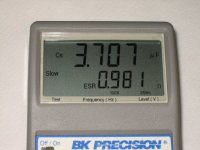
The trusty ESR meter shows a value in line with the published datasheets.ESR meter.jpg

This is the little 4.7uf non-polar I was using for testing.
If I crank 1 amp though it for a couple of minutes, I do feel some heating, but it seems way less than 1W worth. Maybe the can is big enough to dissipate it well, but it's pretty small. Anyway, less heat than predicted is good.

At 2A, I could imagine it might get pretty hot.

So I just need caps with a lower ESR, which means physically larger. A 22uf, 250v one I had handy showed an ESR of around .5 ohms. That's still kind of high. MLCCs have super low ESR, but are very expensive in higher voltage versions. Polyester film caps measured very low too, but for a given capacitance are quite a bit larger than electrolytics and they are also fairly expensive. I'm cheap, so I think I'll just have to find the best trade-off between ESR and cost.

On the driver circuit, I found a TL2843 in the junk box and tried hooking that up. It's really made to drive a transformer, so making it run open loop requries a few extra parts. The TL2842 might be better as it is limited to 50% duty cycle. Getting a 50% out of the TL2843 requires adjusting a pot to get it dialed in, which sort of sucks. It does have some dead time built in, which is nice.

I think I'll keep searching. There must be something that has most of the stuff in one chip somewhere. Ideally I want something that can drive the FET gates directly and has one high side and one low side output. This would be like a synchronous buck converter setup. It would be good if it runs on 5v-12v also.
 
A bootstrap circuit is not too much work, I do remember seeing a few that can drive high-side (or you can get SM highside drivers that work well).

I'll see what I can find - I do remember seeing a few that have inbuilt highside drivers that you only need some external caps to boost the voltage.

Would you prefer DIP or is SMD packages OK?
 
SMD would be OK if they aren't too tiny. DIP is easier to prototype.

I found something called a ST1S10 that has the FETs built in too. That would really drop the parts count. Good for 3A. It would still need a pot or resistor divider to dial in the duty cycle though.

MLCC caps are funny. If you buy small quantities, they are astronomically expensive, but not too bad in lots of over 1000. MLCCs would solve the ESR problem and you could probably run them at very high frequencies. I'm not sure what an upper frequency limit for a schottky diode is.
 
i just looked up 10 uf mlcc's and here is a list of them

http://www.mouser.com/Passive-Components/Capacitors/Ceramic-Capacitors/Multilayer-Ceramic-Capacitors-MLCC-Leaded/_/N-4gzxjZscv7?P=1z0wrkr&Keyword=mlcc&FS=True stocked and non rohs


http://www.mouser.com/Passive-Components/Capacitors/Ceramic-Capacitors/Multilayer-Ceramic-Capacitors-MLCC-Leaded/_/N-4gzxjZscv7Zlls6?P=1z0wrkr&Keyword=mlcc&FS=True stocked and rohs compliant

i see some for as little as 31 cents if you are willing to give up rohs compliance.

i guess you could go ahead and order 1000's and have extras on board to series and parallel for other applications.

and with many resources needed for the parts coming from conflict regions like tantalum you may see a checkbox for conflict free


fechter said:
MLCC caps are funny. If you buy small quantities, they are astronomically expensive, but not too bad in lots of over 1000. MLCCs would solve the ESR problem and you could probably run them at very high frequencies. I'm not sure what an upper frequency limit for a schottky diode is.
 
There are so many of those things, it's hard to sift them.

I took a 4.7uf MLCC and hooked it up to the ESR tester:

Now we're talking. :twisted:

At 9 milliohms, 2A would only need to dissipate 36mW and have a 18mv drop.
With MLCCs, 100v seems to the the economic limit. This might be OK, as you'd want to break up a larger pack into sections anyway. On my breadboard setup, running 1A caused no noticable heating on a tiny little thing that's about 2mm x 4mm.

Another thing I learned from reading the datasheets on the aluminum electrolytics is that at high ripple currents, the life expectancy of the part is pretty short. In actual use, I think the time the caps were subjected to high ripple currents would be relatively short on each charging cycle, but could be like an hour or more on a large pack. The datasheets were indicating lifetimes on the order of 3,000 hours. Less at higher temperatures. This could sort of suck in the long run, as if the cap decided to short out at the end of life, it would be farily catastrophic for the rest of the circuit. I think normally they just sort of go slowly open and loose capacitance though, which would still suck. MLCCs don't seem to have this limitation.

4.7uf seems to work pretty well at 50khz, but since there would be two in series, the capacitance or the frequency would need to double to get the same current. Seems like doubling the frequency should be no problem.

So now it's down to shopping for capacitors. I'm still a bit baffled by the extreme markup for small quantities. Seems like somebody could go into business just buying reels of them and selling small quantites for half the markup.

I need a 4.7uf or possibly 3.3uf at 100v. Mouser had some for $51. EACH! More shopping around is needed.
I need to validate the design before I buy thousands of them, so I need to find a source for like 100ea.
I also need something like a 10uf or 22uf 16v or 25v one for the output of the bridge.

Is there anything tricky about soldering SM versions of these? Seems like they should be pretty hard to burn up.
 
As far as heating goes, I think you're over-estimating the amount of current that's flowing through the caps. When you measured the current before, was it 1A peak? I'd expect the circuit to behave similarly to an RC circuit, so the current through the cap would be a decaying exponential rather than a constant value. The RMS current would probably end up being quite a bit less than the peak, depending on the time constant.

Have you considered driving the circuit with a triangle wave rather than a square wave? That should result in constant current through the cap, which might give you better energy transfer. Creating the waveform would be the trick, though. You'd either have to drive a FET in the resistive region or PWM it at a higher frequency and filter.
 
Driving the FET in resistive region just means you are transferring the heat there. I'd go HF to create the waveform.
 
I don't think all the DC isolation capacitors need to have the same voltage ratings. Specifically, I think the caps only need to be rated for the DC voltage they block plus some margin. So the first two cells would be fine with 10v caps, the next three could use 25v caps, the next 5 cells could use 50v caps, and so on. Further, the two AC power rails could be ground referenced to the middle of a string of cells, this would effectively double the number of cells that could be reached with low voltage capacitors.

For balancing, just power the capacitor coupled cell balancer from the whole battery string. This would apply a light load to all cells, while preferentially charging the lowest voltage cell. Not something I'd want to leave on longer than necessary, but would balance with less loss than shunt resistors.

This is a nice Diode array, Digikey #SD103ASDM-FDICT-ND Higher voltage, and not quite the desired current rating, but array is in a tiny package, and could easily be wired as a full-bridge. 869-1190-1-ND looks like a pretty interesting array too. Both are quite fast so switching losses should be minimal.

Lawson
 
The current measurement is taken after the bridge/filter cap, so it is DC at that point. I imagine the peak current is quite a bit higher than the average. The DC value should be about equal to the actual RMS in the cap.

The triangle wave would need to be more like a square wave with an upward slope because you won't get any current until the voltage exceeds the voltage of the cell you're pumping into. I did consider this. Driving it would be tricky. It could be done with something like a buck coverter ahead of the chopper, so you aren't running the chopper FETs in linear mode. With the right feedback, you could deliver a constant current to the load that was regulated. The buck converter would need to be running at a much higher frequency than the chopper, which is already pretty fast, so that would be hard. There may be another way to do it without wasting a bunch of power, but I haven't thought of it yet. I suppose if the buck converter had synchronous rectification, you could just shape the PWM so the output has the desired waveform and you woudn't need a separate chopper.

I did look at using varying voltage ratings on the caps to save cost, but it gets really complicated to build at that point. I think if I just use all the same ones, I'll save just as much from bulk discounts.

Another thing I did consider was to use lower voltage rated caps, then break up the bus lines that feeds them every so many cells with a single pair of much larger caps to reset the voltage differential. You could also use a separate isolated AC supply for each section and make the secions smaller.

The balance supply should work out to around 5v. I was planning on trying to power this off the battery string to avoid needing another pair of wires. Many of the switching wall warts I've tested work well at voltages starting at around 24v and can go way up to over 240v. These are relatively inexpensive and available off the shelf. Something like the automatic switch I developed for the Ver.4 circuit might work to switch them off at the end of the charging cycle.

DigiKey had some caps that weren't too outrageously priced:
445-5211-2-ND 4.7uf, 100v TDK C4532X7S2A475M
goes for $0.495 ea for 500, $1.79ea for 100 and $3.02ea for 10.
 
More capacitor shopping... Man, there are a lot of these things.

lawsonuw said:
Further, the two AC power rails could be ground referenced to the middle of a string of cells, this would effectively double the number of cells that could be reached with low voltage capacitors.

Since I'm planning on an isolated supply for the balance charger, there's no reason it can't be referenced to the middle of the pack, or module. A 24 series pack or module could then be done with 50v caps.

It seems there is a better selection and price on 50v rated caps.

Here's one I found at Mouser:
Mouser 810-C3216Y5V1H475Z
1206 4.7uF 50V Y5V +80/-20%
1: $0.11
50: $0.085
100: $0.077

Now this is a little tiny 1206 package that is barely big enough to see. I suspect that it won't be able to handle the amount of power I want to run through it, but how do you tell? Datasheets don't say anything about maximum current. These are Y5V too, which don't seem to be as good as the X7S varieties I was looking at. At $0.11ea, it would be OK to parallel them to get the required power and cheap enough to get some for destructive testing. A larger package would be better for hand building for sure.
 
fechter, I'm using some MLCC's in a BMS I'm working on for a client and they're running great at 200KHz in an inductor balancer as the local, low inductance/resistance charge "storage tank". More expensive than the 50V Mouser caps you found but they're X7S and tighter tolerance spec.

But, I'm thinking that they're not really going to be heating up much? My caps are running at 1.2A or so peak, about 400mA avg., and they're not even warm. And they're only 0805 cases.

Try these, 1210 case:
3.3uF, 100V, X7S, +/-10%, 125C max, 10-cents ea./100pcs. : http://search.digikey.com/scripts/DkSearch/dksus.dll?Detail&name=445-5209-1-ND
4.7uF, 100V, X7S, +/-20%, 125C max, 10-cents ea./100pcs. : http://search.digikey.com/scripts/DkSearch/dksus.dll?Detail&name=445-5211-1-ND

Here they are in 2220 case, but more expensive:
http://search.digikey.com/scripts/DkSearch/dksus.dll?Detail&name=445-4524-1-ND
http://search.digikey.com/scripts/DkSearch/dksus.dll?Detail&name=445-4095-1-ND

50V ones would be less expensive.
 
fechter said:
More capacitor shopping... Man, there are a lot of these things.
Yeah, there are. I have a databook from just ONE company that is bigger and almost as thick as my whole Mouser catalog. :shock:
 
fechter said:
More capacitor shopping... Man, there are a lot of these things.

Since I'm planning on an isolated supply for the balance charger, there's no reason it can't be referenced to the middle of the pack, or module. A 24 series pack or module could then be done with 50v caps.

It seems there is a better selection and price on 50v rated caps.

Now this is a little tiny 1206 package that is barely big enough to see.
Being able to use 50V caps is great news! As the knowledgeable Camlight mentions, these will not heat up even with over 2A of ripple current.

Do be sure to get a X7R dialectric though, crappy Y dialectrics drop capacitance really fast with both DC voltage *and* with temperature. You end up with almost zero capacitance if getting even halfway near the specified max T and V limits.

And if you find that those big 1206 packages are small, I'll have to present you with the SON-8 FET drivers I use! Get some reading glasses and good non-magnetic tweezers. You might want to smack me, but I actually *like* surface mount parts more than through hole in general... :mrgreen:

Anyways, I can offer you some 50V, 10uF, X7R MLCC's to try out on your prototype, just PM me your address and I'll slip them into an enveloppe for you.

Pat
 
Datasheets don't say anything about maximum current

most capacitors are used in parallel when used for power and series only for signal coupling or interfacing such as in a sound system between the amplifier chip and the speaker or the input


fechter said:
More capacitor shopping... Man, there are a lot of these things.

lawsonuw said:
Further, the two AC power rails could be ground referenced to the middle of a string of cells, this would effectively double the number of cells that could be reached with low voltage capacitors.

Since I'm planning on an isolated supply for the balance charger, there's no reason it can't be referenced to the middle of the pack, or module. A 24 series pack or module could then be done with 50v caps.

It seems there is a better selection and price on 50v rated caps.

Here's one I found at Mouser:
Mouser 810-C3216Y5V1H475Z
1206 4.7uF 50V Y5V +80/-20%
1: $0.11
50: $0.085
100: $0.077

Now this is a little tiny 1206 package that is barely big enough to see. I suspect that it won't be able to handle the amount of power I want to run through it, but how do you tell? Datasheets don't say anything about maximum current. These are Y5V too, which don't seem to be as good as the X7S varieties I was looking at. At $0.11ea, it would be OK to parallel them to get the required power and cheap enough to get some for destructive testing. A larger package would be better for hand building for sure.
 
The 4.7uf 100v ones from DigiKey are the ones I was looking at before, but they are not 10 cents each!

Digi-Key Part Number 445-5211-1-ND
TDK C4532X7S2A475M size 1812
Price Break: Unit Price
10: $3.02500
100: $1.78750
500: $0.49500
But those do look like ones that would work well.

Mouser version of a similar part:
Mouser Part #: 810-C5750X7R2A475M 4.7uf, 100v
1: $6.54
50: $5.45
100: $3.22
500: $1.08
1,000: $0.84

What's with the small volume pricing on these things anyway? It's crazy.

A 50v rated one from Mouser that's reasonably priced:
Mouser 81-GRM32R71H475KA88L
Murata 1210 4.7uF 50volts X7R 10%
1: $0.65
50: $0.57
100: $0.509
500: $0.458

Right, I did find one datasheet that shows how the capacitance drops with applied voltage and the "Y5" dielectrics look way inferior to the others.

Camlight, good to know heating is not an issue with the little ones. That's encouraging. It's amazing how they can pack that much capacitor into such a tiny package compared to other capacitor types.

So when you guys hand build stuff with these little surface mount jobs, how do you solder them? In the past, I've just held them down with a toothpick to keep them from sticking to my iron and reflowed them with a soldering iron. This requres pre-tinning the pad on the board. What about that paste stuff that comes in a syringe? Anybody ever use hot air? I don't have a hot air station, but I could possibly get one. The toaster over approach sounds cool too if you can do the whole board at once, but I dread the thought of loading up a big board, then dropping it before it gets soldered. :shock:

Mouser and Digikey seem to be about the only places that have any selection of these things. Anybody know of other sources? I'm still not really happy about the price/selection.
 
Back
Top