Help me fix my 48V20Ah LiFePO pack

heathyoung said:
Thats correct - solder the ONE pad you want the pack configured for. Ie. 12S

Reconfigure (MOVE) your cell taps to suit the configuration you need, do NOT solder more than one jumper or you will have smoke. Do not use that schematic. Ie. Tap 1 to cell 1, tap 2 to cell 2 etc etc Tap 11 to cell 11 - DO NOT SKIP CELLS.


OK got that - solder across one tab only.
But here's the thing - there is no 10s tab. Tabs for 11s to 16s on the top board and 6s, 7s on the bottom board.
Perhaps there are others beneath the daughter board that are not visible?

Should I remove the top board or does this mean 10s not possible with this BMS?

Thanks guys,
Glenn
 
That would be a no then. Not supported for 10S, only 6S,7S,11,12,13,14,15. How rude :)

The purpose of these jumpers is to bypass the LVC/HVC signals for the remaining (missing) cells. If you can figure out where these go to on the board, you could solder a link on to fulfill this function.

Its looking a little like you are SOL on this one...

If it were mine, I would be having a good look at the cells you have left, count one string, multiply it by 10 (the number of good strings you have) and then dividing it by 12 (or 16 if you must have 48V) - then using a dremel cutoff disc, remove enough cells to make yourself another 2 strings (or one, since 11s is supported).
 
OK well after a short delay due to a little surgery of my own for thishttp://endless-sphere.com/forums/viewtopic.php?f=1&t=32987 back to pack surgery for batt packs.
My 16s 48V20Ah pack is now a 12s 36V16Ah pack.

5 dead strings were found in the original pack leaving 11 x 20 cell strings strings. These were each shortened to 16cells to salvage cells to create 12 strings of 16 cells each. Each connected for each cell in each string was checked and soldered where necessary. Two subpacks were created for better weight distribution on the recipient frame.

The balance wires were checked and rechecked before connecting to the pack.
Once connected, the voltages of each string was connected at the BMS plugs as initially. All were around 3.3V
During my enforced break (pun intended) I got a new 36V charger from BMS Battery.

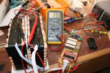
Pic below shows all assembled and initially charging. Going to charge/discharge a few times to check all OK before finishing the packaging.
IMG_3167 (Small).JPG

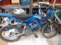
Then when all done, going onto this with a Cell_man DD rear MXUS drive for my kid. But that will be another story........
2011-08-28 17.09.50 (Medium).jpg

Cheers,
Glenn
 
Back
Top