Help with 9c 8x8 rear motor problem.....

itchynackers

100 kW
Joined
Dec 27, 2009
Messages
1,088
Location
Janesville, WI
Background:
I purchased a 9c 8x8 rear motor with the group buy a few months ago. I've ridden about 900 miles on it thus far with zero problems. Wednesday I was 10 miles into my casual ride when the motor just shut down. There wasn't any warning, shuddering, nothing. Sooo, after pedaling my arse back home (oh the agony).

Bike specs when fault occured:
100.1V, 12ah lipo battery
3-speed switch on #1 which is 42% speed, however I was at part throttle cruising on the sidewalk at about 12mph, level surface.
18 fet lyen controller (4115 fets)
9c 8x8 rear disc motor upgraded with 12awg teflon phase wires.

I began to troubleshoot.

LVC in controller?
I had just reprogrammed my controller, so I thought maybe I had a wrong setting. I charged the batts back up. Still no response.
Conclusion: not the LVC.

Bad throttle?
I hooked up the throttle from my other ebike to the faulty bike. Same result...no power.
Conclusion: Probably not the throttle.

Bad controller?
I hooked up the controller to my other ebike. Bike works.
Conclusion: Not the controller.

Bad wiring connection?
I tested wiring connections with an l.e.d. light to see if there was a break somewhere. Lights worked fine.
Conclusion: Probably not a bad connection.

Motor?
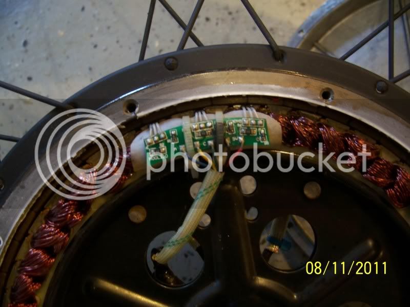
I tested each wire (halls and phase) for breaks with the l.e.d. light. Couldn't find any problems. In fact, when I pulled both covers off, the motor looked, and smelled, brand-new. On the hall side of the motor, I noticed something strange. There is a little circuit board connected to the 3 halls. On that board there appears to be some scorch marks (see pics below). Hopefully that is my problem. Now, what to do next to fix it?

Scorched board with blackened zip tie...
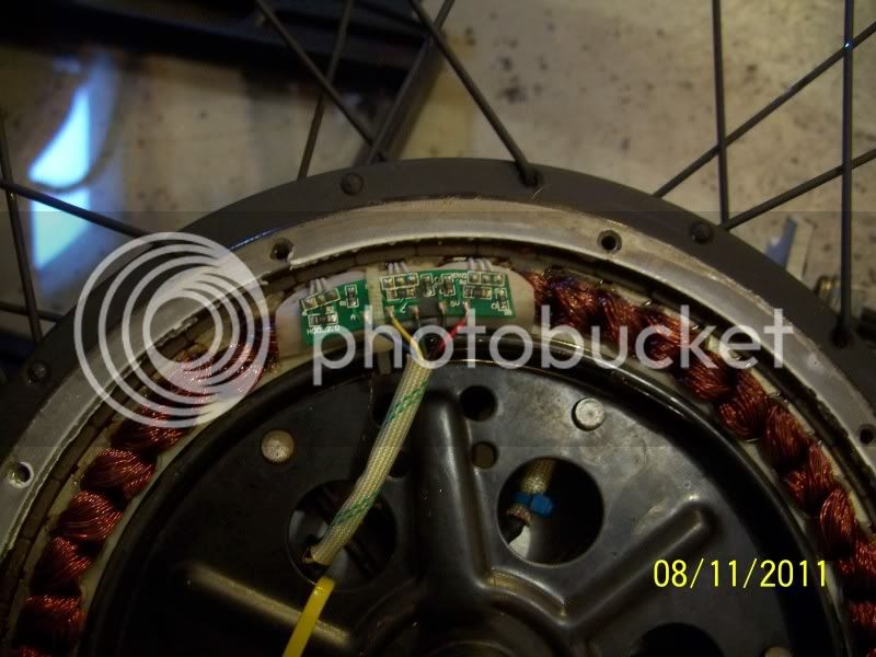
100_2488.jpg


Zip tie removed...
100_2489.jpg


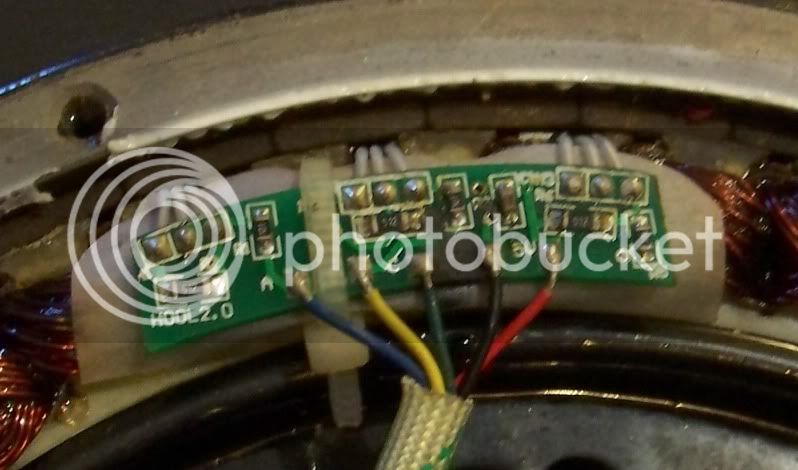
Close-up of board...
100_2489b.jpg


Help!!! What to do?
 
Hopefully one of the members has experience with this.
This is the first PCB failure I have seen.

First up is a closer up shot of that PCB.

If the solution can not be found through troubleshooting (and I wander off someplace...) remind me and I will send you a replacement board. The 9C is well designed and much easier to rework than the X5. I will conformal coat it with silicone too - that should improve reliability a little.

That stated....
Are you saying that the motor passes a hall sensor test?
So... when you rotate the motor you get the correct hall sequence? If that is the case then the problem is not the board.

Please dip into the details of how you analyzed the the hall sensors.

EDIT: Oh, you just tested the wires for breaks. Have a look at THIS thread on how to build a hall tester

-methods
 
I like to build my hall testers so that they can be plugged inline between the controller and hub with no external voltage source.

* Confirms 5V out
* Confirms good ground
* Tests all 3 halls

Then, if I have only a motor with no controller I have the option of adding a 5V source. Often times this is a stator on the bench, so for that i use tiny rare earth magnets to toggle the halls.

Let me know if you would like to borrow my hall tester. It is a POS and it will probably take more time, effort, and money to ship it than just buying a new one :mrgreen: A ghetto version is just 1 LED and 1 resistor

-methods
 
Sorry to Spam... been drinking Red BUll :roll:

You can confirm hall sequence by hooking the controller to the motor, powering everything up, and turning the motor by hand. Put the negative DMM lead to hall ground and probe halls A, B, and C. As you turn the wheel they should toggle. If they do, you are probably set.

There is one sneak failure that is easy to miss here... that is when two halls are shorted! In this case the LED tester helps because it is immediately obvious... if any two halls are doing the same thing at the same time they are shorted. It is very hard to hand-turn the wheel and measure all 3 halls at once since a slight jerk of the wheel will toggle the halls.

-methods
 
You may also want to compare the resistance on the ant size resistors. The ones that are marked as 512 is the 5.1Kohm, I cannot see the other one "1xx" since the focus on your picture is not clear enough. But you get the idea.

The other thing I noticed is the resistor that is marked "512" is connected between the +5V and the hall signal legs. If the resistance is too low or shorted, the +5v will have the potential to send false signal without being triggered.

Lastly, the original 9C (non disc) version does not uses any on board SMD resistors. Therefore, it is possible to bypass the SMD resistors as long as you know the hall sensor specification. The other thing you may want to try is test the motor with another controller. I hope this help. :)
 
IIRC Lyen also sells a tool for debugging hall issues, you may want to ask him about it.

-methods
 
Ok, per some of the suggestions above, I did more testing.

First, I tried to hook the motor up to the other bike. Motor doesn't react.

Second, I couldn't find a 5V source or proper led, so I used my DMM instead to test the halls.
I tested Blk-Yellow, no volts
Blk-Green, no volts
Blk-Blue, no volts

At this point I thought I had forgotten how to test, so I tested the halls on the working bike. All 3 halls register voltage.
So back to the new bike motor to test again. Same result. It seems odd that all 3 halls don't register. I guess that is more evidence pointing toward the board.

Also, I tried brushing off some of the blackish soot on the board. Most of it came off easily. There is still one resistor that I can't read the value on. It looks like it may be damaged.

I tested the resistance on all those resistors. All of the "512" value resistors read 5.1 on my DMM (set to the 20k setting). Those resistors are the ones that are horizontal in the picture. All the vertical resistors are "10-something" I forgot. But they register as 0.1 on my DMM (even the resistor that appears damaged). Well, that is where I'm at right now. Not exactly sure what to do next.

Can the halls be tested at each leg somehow? Maybe with a magnet or something?

Thanks All
 
You have a 5V source... coming from the controller :)

Just so that we are clear:

* the controller was hooked up and powered on
* you could read 5V between the red and black wires on the green PCB
* you read 0V between ground and each of the YGB wires

Measure the voltage from YGB to 5V this time

Measure the resistance from YGB to Ground

Take a high resolution picture of the board... you can use strong lighting and a magnifying lens. Hold the camera up to the lens and move it around until things focus.... er... I suppose I could just look at the one I have here.

-methods
 
Quick reminder on how hall sensors work

* they do not put out any voltage
* they are "latching" so they hold the last state they were in
* They take 5V and GND. The "output" is open collector

Generally they are hooked up as follows

* 5V is run through a resistor to the hall output line
* the YGB wire is attached at the hall output line
* if the hall is tripped it shorts the line to ground
* if the hall is not tripped it allows the 5V to appear on the YGB line
* The resistor is there for current limiting... otherwise when the hall shorts it would try to short 5V to ground and burn up

-methods
 
methods said:
You have a 5V source... coming from the controller :)

Just so that we are clear:

* the controller was hooked up and powered on
* you could read 5V between the red and black wires on the green PCB
* you read 0V between ground and each of the YGB wires

Measure the voltage from YGB to 5V this time

Measure the resistance from YGB to Ground

Take a high resolution picture of the board... you can use strong lighting and a magnifying lens. Hold the camera up to the lens and move it around until things focus.... er... I suppose I could just look at the one I have here.

-methods

Yep, everthing was hooked up as if I were going to ride.

Red to black reads 0.02V at the board, but it reads 4.56V at the controller output.

From ground (black wire) to hall wires gets:
Blk-Green = 0.59V
Blk-Yellow = 0.59V
Blk- Blue = 0.59V all at the board

From red to hall wires gets:
Red-Green = -0.57V
Red-Yellow = -0.57V
Red-Blue = -0.57V

Resistance to ground:
I can't seem to get any reading on these. DMM just says "1."

I can't get a hi-res pic today, as I left my camera at work (to download the previous pics).

Thanks!
 
A bit of a side note: It seems that when I disconnect the hall plug (open circuit) I can get a 4.56V signal on the red-black coming out of the controller, but when I complete the circuit (plug in halls) then the reading goes to 0.02V. Hmm.. Not sure what that means.
 
Lyen said:
You may want to check the resistance between +5V & GND, +5V & phase YGB, GND & phase YGB (yellow ,green, blue). It should helps find you the answer if low resistance is realized.

5V to gnd (black hall wire) (DMM on "200" setting) = oscillates between 13 and 14

5V to gnd (black hall wire) (DMM on "2000" setting) = 186

5V to gnd (black hall wire) (DMM on "20k" setting) = 0.66

5V to gnd (black hall wire) (DMM on "200k" setting) = 05.4

5V to gnd (black hall wire) (DMM on "2000k" setting) = 053
_______________________________________________________
5V to phase grn(2000k setting) = 142
5V to phase grn(200k setting) = 18.0
5V to phase grn(20k setting) = 5.48
5V to phase grn(2000 setting) = no reading
5V to phase grn(200 setting) = no reading

5V to phase yellow(2000k setting) = 133
5V to phase yellow(200k setting) = 16.8
5V to phase yellow(20k setting) = 5.33
5V to phase yellow(2000 setting) = no reading
5V to phase yellow(200 setting) = no reading

5V to phase blue(2000k setting) = 126
5V to phase blue(200k setting) = 16.3
5V to phase blue(20k setting) = 5.25
5V to phase blue(2000 setting) = no reading
5V to phase blue(200 setting) = no reading
__________________________________________

gnd to phase grn(2000k setting) = 045
gnd to phase grn(200k setting) = 07.7
gnd to phase grn(20k setting) = 3.97
gnd to phase grn(2000 setting) = no reading
gnd to phase grn(200 setting) = no reading

gnd to phase yellow(2000k setting) = 034
gnd to phase yellow(200k setting) = 06.6
gnd to phase yellow(20k setting) = 3.80
gnd to phase yellow(2000 setting) = no reading
gnd to phase yellow(200 setting) = no reading

gnd to phase blue(2000k setting) = 032
gnd to phase blue(200k setting) = 06.3
gnd to phase blue(20k setting) = 3.76
gnd to phase blue(2000 setting) = no reading
gnd to phase blue(200 setting) = no reading

Not exactly sure what all that means, but hopefully it helps.

Thanks Lyen!
 
You have got yourself the answer on the very first measurement result. 13-14 ohm indicates a short.

Your meter outputs no readout if the resistance value is out of range.

itchynackers said:
Lyen said:
You may want to check the resistance between +5V & GND, +5V & phase YGB, GND & phase YGB (yellow ,green, blue). It should helps find you the answer if low resistance is realized.

5V to gnd (black hall wire) (DMM on "200" setting) = oscillates between 13 and 14

5V to gnd (black hall wire) (DMM on "2000" setting) = 186

5V to gnd (black hall wire) (DMM on "20k" setting) = 0.66

5V to gnd (black hall wire) (DMM on "200k" setting) = 05.4

5V to gnd (black hall wire) (DMM on "2000k" setting) = 053
_______________________________________________________
5V to phase grn(2000k setting) = 142
5V to phase grn(200k setting) = 18.0
5V to phase grn(20k setting) = 5.48
5V to phase grn(2000 setting) = no reading
5V to phase grn(200 setting) = no reading

5V to phase yellow(2000k setting) = 133
5V to phase yellow(200k setting) = 16.8
5V to phase yellow(20k setting) = 5.33
5V to phase yellow(2000 setting) = no reading
5V to phase yellow(200 setting) = no reading

5V to phase blue(2000k setting) = 126
5V to phase blue(200k setting) = 16.3
5V to phase blue(20k setting) = 5.25
5V to phase blue(2000 setting) = no reading
5V to phase blue(200 setting) = no reading
__________________________________________

gnd to phase grn(2000k setting) = 045
gnd to phase grn(200k setting) = 07.7
gnd to phase grn(20k setting) = 3.97
gnd to phase grn(2000 setting) = no reading
gnd to phase grn(200 setting) = no reading

gnd to phase yellow(2000k setting) = 034
gnd to phase yellow(200k setting) = 06.6
gnd to phase yellow(20k setting) = 3.80
gnd to phase yellow(2000 setting) = no reading
gnd to phase yellow(200 setting) = no reading

gnd to phase blue(2000k setting) = 032
gnd to phase blue(200k setting) = 06.3
gnd to phase blue(20k setting) = 3.76
gnd to phase blue(2000 setting) = no reading
gnd to phase blue(200 setting) = no reading

Not exactly sure what all that means, but hopefully it helps.

Thanks Lyen!
 
I measured the resistance right where the red hall wire and the black hall wire meet the green circuit board. Actually on the soldered part of the board. I'm still not sure what that means. Does it mean there is a problem with the board? Or is it somewhere else along the red or black wire?
Sounds like we are getting close!

Thanks You,
Adam
 
It means you are shorting out your 5V source. This can happen anywhere on the board. Most likely place though is at the hall sensors or in the cable.

Starting with the controller disconnected....

1) Desolder the red wire. Measure from the red wire to where the black meets the circuit board. If there is a short the problem is in the cable between the connector and the board

(solder the red wire back on if there was no short)
Now we know the short is somewhere on the board

visually inspect the board for the short
Visually inspect each of the three hall sensors for the short

Now... It is unlikely that there are any resistors going directly from 5V to ground, so we dont have to look for any of those. I doubt there are any caps on the board, but if there were I would check them.

2) Remove the hall sensors from the board one at a time

This is assuming the short is in one of the hall sensors.... I will have to go out to the garage, grab a stator, and see how I would go about this.

be right back

-methods

P.S. 99% of the time problems like this are so obvious that you cant see it.
 
OK - looking at my stator a few things come to mind....


1) The scorch might have nothing to do with this.... the most likely place to find a short would be in the cable running from the board to the connector, through the axle. That is an easy test, so perform that first.

2) Turns out there is a cap on the board. It is the brown part marked C1. That is the most likely place where you would find a short on the PCB. You can remove that cap easily by getting both sides of it hot and then "sliding" it off the board. If you have trouble with surface mount I can guide you through soldering it back on.

Here is a picture from my Cell phone :wink:
No magnification
Click it to go SUPER SIZE


-methods
 
A quick look at the circuit board shows the following:


1) The hall sensor pads are as follows: +5V, GROUND, SIGNAL
2) The signal line has a 5.1K pull-up resistor to 5V
3) The signal line has a 100 ohm resistor in series with the YGB wire
4) There is a local capacitor to stabilize the 5V plane - it is probably rated at a low voltage so it could have shorted!


I dont think you will need to desolder the halls... I am pretty sure you will find your problem in the cable or with the capacitor. A high quality picture like the one I posted makes all the difference... I stare at circuit boards all day and if you show me a good picture I will see a problem if it is there.

-methods

P.S. Check the legs of the halls where they meet the board and where they meet the hall bodies. The left two legs... any bits of metal?
 
I tried to look closer at your board...

What does the brown component (C1, right above the black wire, with R3 written to its left) look like?
The board will work fine with out that.... If it looks all puffy or there are any cracks just wipe it off the board.

I think your scorch marks could just be the zip tie rubbing on the wall "dusting" the board. Do you see any actual scorch marks on the board? See how nice my cap looks? Yours should look just the same... brown and smooth.

-methods
 
So it turns out that the board pops right off of the housing.

I removed the two zip ties (actually... they just rotted off....) and wiggled the board. The hall sensors are just fitted into the slots. Looks like there was glue, but it has burnt off. With the board off you can troubleshoot the hall sensors.

since my board is now off I can ship it to you if you give up too. Plug and play, just solder the 5 wires on and slide the halls into the gaps.

-methods
 
Here is what the bottom of the board looks like... in all its glory

(again, click to super size)


-methods
 
yes.
The only thing the board is doing for you is managing the noise a little, protecting the halls a bit, and providing compatibility with a wider range of controllers. It also makes for a clean assembly that can be pre-produced on a jig and slid into place...

Besides... if we pitch the board now what will we learn :)


-methods
 
methods said:
I tried to look closer at your board...

What does the brown component (C1, right above the black wire, with R3 written to its left) look like?
The board will work fine with out that.... If it looks all puffy or there are any cracks just wipe it off the board.

I think your scorch marks could just be the zip tie rubbing on the wall "dusting" the board. Do you see any actual scorch marks on the board? See how nice my cap looks? Yours should look just the same... brown and smooth.

-methods

Ok, did a bit of testing. I cleaned off the black dust as best I could. The brown cap doesn't really looked puffy or cracked. It's a bit dirty, but appears intact. After cleaning the board, I can't really say there is any scorching on the board.

I inspected the halls and connections the best I could. It's hard to see underneath the plastic sleeves on all the hall legs, but they looked good.


I desoldered the red wire and tested for voltage. 0.02V to ground. So I disconnected the halls connector outside the motor and red to black measured 4.51V, so it is good coming out of the controller to the connector. I connected the connector again, and tried to measure downstream of the connector, but still outside the motor. Still got 0.02V. Hmm. So now I desoldered the black wire from the board too. Then measured the voltage at the ends of the 2 wires. Still got 0.02V. Soo, it seems like there is a short in the red wire somewhere between the connector (outside motor) and the end of the wire at the board. Is that what it seems to you guys? If so, the board may still be good, and I'll have to tear down the wires into the motor tomorrow.

Methods, your camera pic is great. My blackberry is crap compared to that. Even my 8 Megapixel camera couldn't focus that good. Let me know if you think the red wire is the problem.

Thanks!
Adam
 
Back
Top