lepton
1 W
Nice work! Major kudos. Is the motor as loud in person as it seems in the video?
 . i really do have a bad temper.
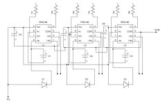
Could you show the schematic diagram?dirty_d said:this is the driver board i made for it, if anyone wants the schematic or pcb layout files just ask.
johnrobholmes said:Got some sensors on order today, here is to hoping I can duplicate this with one of my motors! If so, I think we may have a HUGE opening for sensor based outrunners that could work with current bike controllers assuming the commutation speed is up to the task.