HP ESP120 48V (51.4V) 57A 3KW Server Supply Thread

I'm pretty sure that this supply will drop voltage.. Just not a whole lot. Test it.

Why not just stop at predefined intervals? It's very essy to set timer to allow voltage to come to rest. I don't see an issue charging a 50.4V pack with 51.4V. Arduini will shut it off completely and it will have no chance to over volt. Plus near 90% soc, won't the charge rate be like 5-15A?

Regarding monitoring the whole pack, I don't see a real danger at 90%, but I'll be careful and watch it. The best setup would be a bms.

I would have to make a voltage divider and scale a range of about 15V down to 5V for the arduini to read. Easiest way to do this? Op amp? Isn't the cell near the negative end if the pack always the lowest? Could reference lowest cell?
 
Usually these PSU.. and just like the Pioneer Magnetic and Meanwell 750, 1000 and 1500W i have, are all constant power and CC-CV limiting.

When i search for the voltage adjustment ( when no pot is availlable), i look for the little pcb traces that are connected to the DC output. usually these little low current trace are the output voltage sensing. These traces connect to resistor divider and near them there is often a LM324 op amp for the feedback. To check if that work, i simply connect a light load to the output, measure the voltage while i try to parallel a little 10kohm resistor to few f them on the resistor divider of the feedback section.

It might take time but once you reach the right resistance, than the output voltage change. ( it might rise or fall)

In the case where paralleling a 10k resistor to the right resistor you found is making the output voltage to fall, what you need to do is to onsolder that resistor and to install a pot with like 200% the value of that resistor so you will have the right voltage span to increase the voltage to the desired value.

In some case it might makea strange noise in the transformer section, and it indicate that you reach the limit of the tolerance and stability of the psu.

I also use that method but for modifying the current limit of these psu.

Actually i'm working on my 2 RSP1000-48 from meanwell to reduce their current limit from 21A to 15A to be able to connect both psu in serie and get 100.8V at 15A and be able to use it on a normal 15A 120V socket.

Doc
 
Hi,

ZOMGVTEK said:
For 12V I really like the ESP135's... Theyre rated at 47A @ 12.15V, and will go up a few volts with mods, if need be. Simple IEC in, bend 3 pins into each other to turn on, and simple outputs.

The ESP135's use the same 3 pins and outputs?:
IMG_5828.JPG


You soldered on the output wires and sealed it by filling the area with silicon seal?
 
The ESP135's have a 15A IEC for the power inlet, and a similar but not identical configuration for the output. You need to connect different pins to get it to power on, that info is readily available by searching around for ESP135. You can also raise the output voltage to about 13.4V.

On my ESP120, I soldered some 14/2 romex onto the power input terminals, and covered it it hot melt. That was just to test the supply out, if I put it into normal use, that would be removed and upgraded to something a bit more rugged with a plug. The romex was just stripped and shoved into two adjacent breakers.
 
Hi,

For connecting three pins in a horizontal or vertical row RC Servo extension cables work (push them on, cut and strip the wires, and twist them together):
10x-rc-extension-cord-300mm.jpg


Unfortunately they don't work with the HP ESP-135 :( 
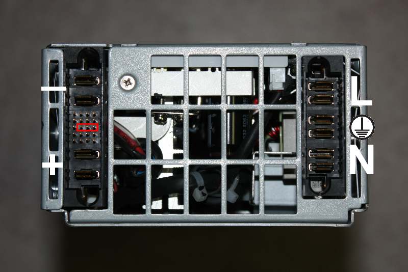
(the 3 pins that need to be connected are in line diagonally).
 
I only used that connector on the ESP120, since I wasn't sure what I wanted to do with it. For the ESP135's I bent the pins together and soldered them. No need for a plug, why would I want to turn it off? I just plug it in when I want it on, an its on. To turn it off, you remove the power plug...

Here is what they look like...

6289690286_3f554993f5_b.jpg


6199798968_f4d1f45d04_b.jpg


I just bent the 3 pins together, lightly soldered them, and covered it in glue.
 
It sounds very foolish, but I can't find a datasheet on this. So i'm not sure how to interpret the lights on the front.

When I short the three pins to activate "on" I get the green power light to be on, but I have a blinking yellow information triangle light. When I don't short them, I have a blinking green light.

In neither case do I get DC output.


Anyone know what's going on? This refers to the ESP120 (51.4v 57A), running off 208VAC (don't ask me, I don't understand how phase 1 is 110v and phase two is 112v and we get 208v when we combine them. But thats because I don't understand the basics of real-word electricals.)

Edit: I found the short datasheet again, http://www.rcgroups.com/forums/showthread.php?t=1625284, but didn't find useful information about the lights in it.
 
I wish Luke would chime in on his efforts with this thing..

check out this guy:
http://www.ebay.com/itm/HP-74840-001-Power-Enclosure-4-Batt-ESP120-226519-/110940122887?pt=US_Server_Power_Supplies&hash=item19d48bef07#ht_2320wt_1299
 
That ebay one looks like just 6 of these in a case? I suppose that is itself kind of interesting.

I'm wondering if anyone has useful information about the yellow information triangle dot led on the front. I really wish I could understand why mine isn't putting out DC output. There's a marked high pitch change in the PS when I short the three pins, and the yellow triangle led starts blinking. So at some step things are being repressed, I just wonder which. Something is happening, though.

I might fiddle around a bit more. I'm not really getting anywhere though, my german isn't good enough to read the only source that seems to have deeply analyzed this PS (There's a google group from a german group that did a lot of work with this...even building a board that automatically shuts it off at a certain voltage [for charging RC batteries] and it adjusts the voltage. Several ES members were talking about doing that and if someone could just figure out what the german guys did, it might save a lot of work.)
 
I'm not sure if I should be reposting what I posted to another thread, but this would be the more on-topic location to post it, although it was my secondary location I thought of.

Anyway, I thought I would post two links from the german guys who worked on the ESP120.

Essentially they made a holy grail system for the ESP120....28v-60v, 0-57A....That's pretty awesome, even if the accuracy is only rough.

http://translate.google.com/translate?hl=en&sl=de&u=http://elweb.info/dokuwiki/doku.php%3Fid%3Dhp_3kw_netzteil_als_lader&ei=iGt4T4_yGOnL0QHnm7mtDQ&sa=X&oi=translate&ct=result&resnum=1&ved=0CCUQ7gEwAA&prev=/search%3Fq%3Dhp_3kw_netzteil_als_lader%26hl%3Den%26safe%3Doff%26biw%3D1400%26bih%3D867%26prmd%3Dimvns

http://www.lifepohandel.de/epages/63129206.sf/de_DE/?ObjectPath=/Shops/63129206/Products/%22Steuerplatine%20f.%20HPNT%20V2.2%22
 
I just found a thread on lowering the voltage down to like 44V if needed. I think a digital pot, shutn and arduino would easily make this work well. Thinking about buying a couple since they are so cheap.

http://www.rcgroups.com/forums/showthread.php?t=1823759
 
Anyone successfully make a current limiter for this yet?
 
Yes, I have a pair of the german CC/CV kit mentioned a few posts up.

It's a pretty simple circuit, I will snap pics of the PCB and schematic with component values for you, they give all that info and an install guide with the kit.
 
liveforphysics said:
Yes, I have a pair of the german CC/CV kit mentioned a few posts up.

It's a pretty simple circuit, I will snap pics of the PCB and schematic with component values for you, they give all that info and an install guide with the kit.
OK so is it just controlling voltage to try to regulate current? IE if you connect to a dead short it will still pop the server supply?
 
liveforphysics said:
Yes, I have a pair of the german CC/CV kit mentioned a few posts up.

It's a pretty simple circuit, I will snap pics of the PCB and schematic with component values for you, they give all that info and an install guide with the kit.


I was looking into purchasing one of the kits from the website . https://shop.strato.de/epages/63129206.sf/secbbf7ec101d/?ObjectPath=/Shops/63129206/Categories/Ladegeraete
I noticed that you have already purchased one of the kits, can you give any feedback on the instructions / paperwork to install the circuit as I dont speak German and just want to make sure the kit is worth purchasing,
Also do you know whats the difference between the V2.1 kit and the V2.2 kit

any help you can provide would be greatly appreciated

Did you end up getting any photos of the install and finished product would love to see this
 
Hello,

I got this HP power supply , i need to use it with a less output voltage ( 48-50V) Does anybody knows how to adjust the output voltage to 48V - 50 V Maximum ?

Thanks

Gio
 
liveforphysics said:
Yes, I have a pair of the german CC/CV kit mentioned a few posts up.

It's a pretty simple circuit, I will snap pics of the PCB and schematic with component values for you, they give all that info and an install guide with the kit.

Hey Luke, did you get a chance to take this pic?

I was wanting to buy this kit but it seems very costly (75 euro) for what it is..

think I might try an arduino based controller with a simple PID control loop to adjust the voltage output of the PSU based on current measurement, to maintain the current at an adjustable setpoint.

That PCB schematic and component values would give me a better idea of how to implement this.
 
Guys I have 2 of these and got them working and wired them in series with a 12v MW but what happens when I hook at 30 amp limited MW in series with them so the max voltage is 116 but say my pack is below 100v will these try to push 57 amps I think this will be ok above the added together voltage of the 2 ESP120s which is 102.8v total, but when its below will it just shut them down or blow my MW???
I would be looking to charge from ~80-116v.....
 
Just about there. When the voltage is below what the 2 HP server supplies produce on their own I have to make sure I have a good diode across the 12v supply so it doesn't get reversed. My 50 amp switching supply is on order. :)
 

Attachments

  • IMG_20140621_194304[1] (800 x 1067).jpg
    IMG_20140621_194304[1] (800 x 1067).jpg
    143.4 KB · Views: 3,692
Arlo- When Doug was still here yesterday (with a broken collarbone from his race), I gave him my CC/CV modding kit for the ~$30 3kW HP server supplies.

It makes them 28v-60v, and 0A to 57A CC/CV power supplies.

He is bringing the kit to you.
 
Thanks man. I managed to decifer doug's email ;). I will try to reverse Enginery this kit and post a diy version but will likely be fall when I get that far. For now I will post pics asap.
 
Arlo1 said:
Thanks man. I managed to decifer doug's email ;). I will try to reverse Enginery this kit and post a diy version but will likely be fall when I get that far. For now I will post pics asap.

You could make your board leverage some cheap ebay power meter to aid in easy instrumentation and adjustment.

http://www.ebay.com/itm/DC-0-200V-0-150A-Programmable-Meter-Controller-Volt-Amp-Power-Ah-Auto-Shut-Down-/181209317394?pt=LH_DefaultDomain_0&hash=item2a30eac012
 
Cool. I will look into this. I have 2 v2 CA,s kicking around I wonder if I can use one of them.. It would be neat to have it communicate with the bike and know what's going on from there.
 
liveforphysics and Ario,
Just getting my head around the ESP120 what an amazing gift from HP to us! Was going to attempt a charger with 8x12V in series a little scared of so many ungrounded and floating supplies...

I would hapily reverse engineer the cc/cv kit for you photos photos top and bottom. A proper charger would be great but out of $ due to f! deal with battery supplier.
I assume this can be turned into a LiFEPO4 charger with V/A monitoring, digital pots and an arduino (Which begs the question that this must have been done already) (28x100AH sinoploly)

Otherwise where could I get the kit in a hurry... Now to see if my friend at the computer recycling company has seen these beasties, he has given me plenty of 12V which have heaps of potential as dc-dc for ev.

Cheers.
 
Back
Top