You are using an out of date browser. It may not display this or other websites correctly.
You should upgrade or use an alternative browser.
You should upgrade or use an alternative browser.
I guess I need to make 72v 35ah battery pack
- Thread starter Theodore Voltaire
- Start date
Theodore Voltaire
1 GW
I see what you mean. According to the chart 0.15 x 8 is only equivalent to 7g wire. 0.3 is like 14g. 14g seems small for 20 amps? Maybe use 0.3 with 0.15 welded on top?This depends on your pack layout. Perhaps you can draw it, or at least describe it? I just skimmed through the thread quickly, so perhaps you've stated it and I just missed it, but it seems like you're planning a 100a capable pack. Meaning your total series connections need to be able to handle 100a. How many strips of nickel will be in the parallel connections? I couldn't tell for sure from your descriptions in the above posts whether you're planning 7p or 10p.

Nickel Strip ratings
Hi All, I am just wondering if someone can point me to a chart or resource that will show me the current ratings for this: https://eu.nkon.nl/accessories/battery-solder-strip/nikkel-batterijpack-verbinding-soldeerstrip-27mm.html nickel strip 27mm x 0.15m. I have asked Nkon and they don't...endless-sphere.com
If you follow this chart, you'll see that .15x8mm nickel is only good for about 5 amps. To safely carry 100a, you'd need 20. If you're planning 10p, and there's 10 series connection points between all your parallel groups, then it's "possible" to get what you need by stacking 2ea .15x8mm strips per nickel connection. If you're doing 7p, I wouldn't recommend stacking 3 strips.
My welder came today. I'm not sure how thick of metal it can weld. I didn't realize I had to put it all together. It's like a test, if you can't figure it out put your hands up, and back away from the battery box.
Attachments
Theodore Voltaire
1 GW
I'm now thinking of 2 ways of building a 72v pack that would fit my space.
Plan a
7 parallels of groups of 20 cells in series = 72v, 140 cells
or
Plan B
groups of 7 parallel cells, in 20 series, = 72v 140 cells
I'm guessing either method would end up the same, but I'm not sure. Would one way be better then the other?
Plan a
7 parallels of groups of 20 cells in series = 72v, 140 cells
or
Plan B
groups of 7 parallel cells, in 20 series, = 72v 140 cells
I'm guessing either method would end up the same, but I'm not sure. Would one way be better then the other?
docw009
1 MW
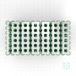
I believe that the ideal layout for a battery to stack each group in one column. Then place the groups end to end, so that the series current flows directly from one cell to the next. Here is how it would look for a 13S-7P. Each horizontal section of nickel needs to be thick enough to carry 1/7 of the battery current, The vertical connects are only for small parallel currents, so don't have to be very heavy, At the positive and negative ends of the array, you have to connect the power cables so the current flows evenly out of all 7 cells.
I do not like stacking strips, I think they can be problematic when you do more than two. However, you have a big welder so it shouldn't be a problem.

I do not like stacking strips, I think they can be problematic when you do more than two. However, you have a big welder so it shouldn't be a problem.
Theodore Voltaire
1 GW
I'm finally starting to understand how, and why, to build a pack with more parallel cell groups as opposed to all series cell groups. Apparently building with parallel cell groups in series, instead of single cell groups in parallel you get less sag. I hadn't thought about that before, but it makes sense to me. If I'm wrong about this feel free to say so. Nothing is set in stone.I believe that the ideal layout for a battery to stack each group in one column. Then place the groups end to end, so that the series current flows directly from one cell to the next. Here is how it would look for a 13S-7P. Each horizontal section of nickel needs to be thick enough to carry 1/7 of the battery current, The vertical connects are only for small parallel currents, so don't have to be very heavy, At the positive and negative ends of the array, you have to connect the power cables so the current flows evenly out of all 7 cells.
View attachment 351829
I do not like stacking strips, I think they can be problematic when you do more than two. However, you have a big welder so it shouldn't be a problem.
I'm now thinking in terms of 20 groups of 7 parallel cells each. That still ends up 72v and 140 cells.
Last edited:
Theodore Voltaire
1 GW
Theodore Voltaire
1 GW
Ok moving slow, but I finally got to the point where I can calibrate my KWelder.
First problem, I can's seem to get it too calibrate. When I move through the menu everything seems good. When I get to the point were it says to touch the probes together, and it the button resistance is in spec 2.89 MR but it still doesn't calibrate.
I'm wondering it the used car battery I'm using is the culprit. It was given to me by a friend after he bought a new one for his can. When I first checked i's voltage it was only about 9v, but after charging it for a while it holding 12.8v for over a half hour.
What makes me suspicious of the battery is when I get to the last calibration step, I short the probes, hit the button, and the first thing on the display is, under current, then it scrolls through 4 items. R 2.89, STD 46.0, I 496a, T 28.9c
The bare minimum is 800 A for proper functioning. 1200 to 2000 A is the recommended range. 496 A is inadequate. That battery is very tired.What makes me suspicious of the battery is when I get to the last calibration step, I short the probes, hit the button, and the first thing on the display is, under current, then it scrolls through 4 items. R 2.89, STD 46.0, I 496a, T 28.9c
Last edited:
Theodore Voltaire
1 GW
Thank you very much for the reply. That's very reassuring, I was going to try a new battery next.The bare minimum is 800 A for proper functioning. 1200 to 2000 A is the recommended range. 496 A is inadequate. That battery is very tired.
Theodore Voltaire
1 GW
I bought a new battery at Walmart, and that solved the calibration problem. Now I'm going to practice. After a little trial and err l decided 130j worked pretty good on 0.15
Theodore Voltaire
1 GW
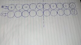
Since my first design was a flop, this is my latest new and improved design. I'm hoping this one won't be quite as embarrassing. The reason it's like this is because of space limitations. 20s 7p. In the end it will be 5 cells wide, and 2 cells tall, and 14 cells long, 140 cells in all. The red box is the shape of the battery compartment. I'm thinking I should fold the battery pack in half along the red line making it 5 cells wide, unless anyone knows a better way. I'm not exactly sure how to connect the 10th series to the 11th. I'm thinking maybe 3 8g wires soldered like in my diagram. I want to get this right so I don't mind constructive criticism. Fire away. 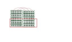

Theodore Voltaire
1 GW
I'm ready to order the battery cells. I'm planning to use Samsung 50s x 160, that will give me 20 extra cells. This is the first time I've ordered battery cells. When I search them the first 2 online stores are 18650batterystore, and IMR Batteries. Does anyone know a better place to order from?
Theodore Voltaire
1 GW
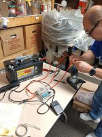
Last night after getting my welder to calibrate my good friend and I started testing it's out. If you've ever worked with an engineer then you know what a pain in the ass they can be to work with. He's a retired double E from Texas Instruments. Even though he has no experience building battery packs he loves to remind me that he knows more then I do. He doesn't know about you guys standing behind me though. He conveniently forgets that when we first failed to get the welder to calibrate, I was the first one to guess it might be a worn out battery.

Last edited:
eMark
100 kW
Your phrasing may be confusing ... perhaps why no others have replied to above quote.It may have been less confusing as ...I'm finally starting to understand how, and why, to build a pack with more parallel cell groups as opposed to all series cell groups. Apparently building with parallel cell groups in series, instead of single cell groups in parallel you get less sag. I hadn't thought about that before, but it makes sense to me. If I'm wrong about this feel free to say so. Nothing is set in stone.
"to build a pack with 7 cells in each parallel group instead of just 5 cells in each group would minimize any voltage sag during a max discharge load".
When referring to the cells connected in series a "string" is preferred and when referring to the cells connected in parallel a "group" is preferred.
"I'm now thinking in terms of 20 cells in each series "string" with 7 cells in each parallel "group" (20s7p) for a total of 20 such parallel groups of 7p. That still ends up 72v (nominal cell voltage of 3.6V)".I'm now thinking in terms of 20 groups of 7 parallel cells each. That still ends up 72v and 140 cells.
All 140 cells are serving as both a cell in each of the 20 series strings as well as the 7 cells in each of the 20 parallel groups. 280 "series" bus bar connections and 280 parallel bus bar (overlapping) "group" connections (140 on each cell end). Each of the 140 cells serves a dual function as both a cell in each series string as well as a cell in each parallel group.
Question(s): Should the parallel bus bars overlap the series bus bars or vice versa? Which bus bars (parallel or series) should preferably be spot welded first or doesn't it make any difference? Is it better to completely assemble all 140 cells and spot weld both the series and parallel bus bars at the same time?
Theodore Voltaire
1 GW
Thanks a lot eMark, I really appreciate you taking the time to try and teach me better terminology. I'll try and remember to use these terms, strings, and groups so we'll all be on the same page.
docw009
1 MW
I wouldn't fold a stack of 35 cells on top of another. It's hard to spot weld them and fold them straight, and you have to adjust the strips to fit an insulator between the top and bottom. I've done it, and I get crooked stacks. If I have to stack them now, I would extend separate strips of nickel from each half, and solder them together later.
If you can get the H-pattern in pure nickel, you get both parallel and series at the same time.
You are going to have three long strips where you have to bolster the nickel. The first two are the positive and negative ends where 7 cells have to flow into B+ and B-. The third will be between groups 10 and 11 where 14 cells in a row are connected. In my opinion, making it carry 40A is tough enough, and you want 100A? Figure on adding a lot of copper wire.
Theodore Voltaire
1 GW
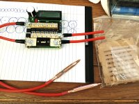
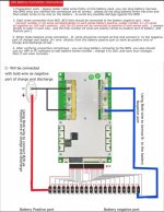
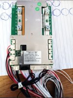
This has always been a question in my mind. After having the bms in my hand and seeing how it's wired, now I understand.BMS doesn't have a "P" number, only S, because all cells in P are already connected together and thus use the same balance/sense wire from the BMS.
Theodore Voltaire
1 GW
Thank you for sharing your experience. I like the idea of not having to fold the halves together, and I was already looking into finding some H pattern nickel.I wouldn't fold a stack of 35 cells on top of another. It's hard to spot weld them and fold them straight, and you have to adjust the strips to fit an insulator between the top and bottom. I've done it, and I get crooked stacks. If I have to stack them now, I would extend separate strips of nickel from each half, and solder them together later.
If you can get the H-pattern in pure nickel, you get both parallel and series at the same time.
You are going to have three long strips where you have to bolster the nickel. The first two are the positive and negative ends where 7 cells have to flow into B+ and B-. The third will be between groups 10 and 11 where 14 cells in a row are connected. In my opinion, making it carry 40A is tough enough, and you want 100A? Figure on adding a lot of copper wire.
Theodore Voltaire
1 GW
eMark
100 kW
As you know that's a BIG No-No ... Looks like there is no protective shrink wrap on the cells. You can't have the bare metal cans touching each other.
If you were going to stagger the parallel groups (to save space) you should have two or three shrink wraps on each cell. Were you also planning on gluing the cells together ... Which glue to join cells ?
If you were going to stagger the parallel groups (to save space) you should have two or three shrink wraps on each cell. Were you also planning on gluing the cells together ... Which glue to join cells ?
docw009
1 MW
I would avoid glued cells. There's a possibility of a short circuit between the PVC layers. It's probably OK for small batteries, maybe 4 or 6 cells. I am hoping the picture shows cells with clear shrink wraps.
Theodore Voltaire
1 GW
This is not my work, I just glommed this picture because of the copper being used to connect the string. I'm planning to use plastic cell frames in my pack. I was wondering if using copper like this allows higher current than nickel strips alone, or if maybe copper is a bad idea?Is this considered a good way to connect your parallel groups in a string.View attachment 352898
A-DamW
1 kW
Yes, copper sandwich good, read yer' heart out:This is not my work, I just glommed this picture because of the copper being used to connect the string. I'm planning to use plastic cell frames in my pack. I was wondering if using copper like this allows higher current than nickel strips alone, or if maybe copper is a bad idea?
"Copper/nickel sandwich" buses for series connections
Theodore Voltaire
1 GW
Oh yeah, that's very interesting, thank you. I think I need to order some copper sheetYes, copper sandwich good, read yer' heart out:
"Copper/nickel sandwich" buses for series connections


