I want to know who these MOSFETs are!

wcwc98

10 µW
Joined
Jan 6, 2024
Messages
5
Location
busan
Hello! everyone!
I'm just a user who is getting a lot of information from here.

After learning about ES recently, I learned about shunt mod and MOSFET's specifications while getting various information about diy.
but when I looked at my controller, there was too little related information and I couldn't find the manufacturer and specifications of the internal MOSFET!

I've checked all the symbols of the manufacturers on the Internet, but I couldn't find them, and I can only estimate the specifications through the marking code

Does anyone know about this MOSFET?

my bike is cmacewheel's rx20max
and controller is zf-004(I guess zhifeng's)
it is 48v 18a(continuous 9a) dual motor controller
so, it has 12(6+6) mosfets
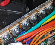
PXL_20240223_141310475~2.jpg

I guess the controller is only for 48v, so 055 is the limit voltage and 09 is 9a.
Then... could it be a fake marked mark given that the phase current is higher than the battery current consumption, and specification that doesn't have much leeway?
 
Hello! everyone!
I'm just a user who is getting a lot of information from here.

After learning about ES recently, I learned about shunt mod and MOSFET's specifications while getting various information about diy.
but when I looked at my controller, there was too little related information and I couldn't find the manufacturer and specifications of the internal MOSFET!

I've checked all the symbols of the manufacturers on the Internet, but I couldn't find them, and I can only estimate the specifications through the marking code

Does anyone know about this MOSFET?

my bike is cmacewheel's rx20max
and controller is zf-004(I guess zhifeng's)
it is 48v 18a(continuous 9a) dual motor controller
so, it has 12(6+6) mosfets
View attachment 349560

I guess the controller is only for 48v, so 055 is the limit voltage and 09 is 9a.
Then... could it be a fake marked mark given that the phase current is higher than the battery current consumption, and specification that doesn't have much leeway?
This is the closest I could find - https://www.fet.discoveree.io/datasheet.php?view=pdf&file=crmicro/crst055n09n.pdf The first two characters on that datasheet are the same as the manufacturer, so maybe that part of the code is about who makes it rather than what it is... if that is the part it's rated quite a lot higher than that - 90V/130A.
 
Keep in mind that the FET ratings are for phase current, which is a lot higher than battery current.

The shunt monitors battery current, and that's what hte rating on the controller label will indicate.

So you can't directly use the FET capabilities to know what you could modify the controller to handle.

When you mod the shunt, the controller has no idea what current is actually flowing, and can no longer protect any of it's parts, or your battery, against overcurrent, so it is easy to destroy the controller and even the battery (if the battery does not have working overcurrent protection, the BMS or the cells can be damaged, and it can happen without ever showing a sign of the damage until catastrophic failure happens, which may not be while you are using the system).

These things will be made with the very cheapest parts they could possibly get taht will just barely do what they say they will, and sometimes not even that. So modifying it to force it to do more than it was built for often doesn't have the results you wanted or expected.

The FET voltage isn';t just about battery voltage. It's about the phase voltages fed back from the motor during operation, especially during regen and/or sudden motor shutdown, whcih can be much higher than battery voltage. If you use a higher battery voltage than the controller was setup for, the feedback phase voltages from the motor can destroy the FETs. (often in a way that locks up your motor, so if that's in a wheel it can lockup the wheel, and cause you to crash).
 
This is the closest I could find - https://www.fet.discoveree.io/datasheet.php?view=pdf&file=crmicro/crst055n09n.pdf The first two characters on that datasheet are the same as the manufacturer, so maybe that part of the code is about who makes it rather than what it is... if that is the part it's rated quite a lot higher than that - 90V/130A.
Wow thank you so much!
This is worth a try!

I'm not sure yet, but my original plan was to replace it with an esc that handles higher currents!
 
Keep in mind that the FET ratings are for phase current, which is a lot higher than battery current.

The shunt monitors battery current, and that's what hte rating on the controller label will indicate.

So you can't directly use the FET capabilities to know what you could modify the controller to handle.

When you mod the shunt, the controller has no idea what current is actually flowing, and can no longer protect any of it's parts, or your battery, against overcurrent, so it is easy to destroy the controller and even the battery (if the battery does not have working overcurrent protection, the BMS or the cells can be damaged, and it can happen without ever showing a sign of the damage until catastrophic failure happens, which may not be while you are using the system).

These things will be made with the very cheapest parts they could possibly get taht will just barely do what they say they will, and sometimes not even that. So modifying it to force it to do more than it was built for often doesn't have the results you wanted or expected.

The FET voltage isn';t just about battery voltage. It's about the phase voltages fed back from the motor during operation, especially during regen and/or sudden motor shutdown, whcih can be much higher than battery voltage. If you use a higher battery voltage than the controller was setup for, the feedback phase voltages from the motor can destroy the FETs. (often in a way that locks up your motor, so if that's in a wheel it can lockup the wheel, and cause you to crash).
I understand your concern and what you mean.
My original plan was to safely replace esc with something better...

but it's a minor "joke" to try before that.
I set up an ampmeter on my bike and a digital thermometer from my friend's computer case,
so it probably won't kill me!

I just make little more amps between 1.1x and 1.35x. Through a parallel connection!
 
These seem to be commonly found in e-bike controllers, are pretty durable and don’t seem to have many issues. They can be improved by adding thermal paste to improve heat transfer. I think my common unmodified 12 FET KT 40a controller uses these and barely gets warm.
 
These seem to be commonly found in e-bike controllers, are pretty durable and don’t seem to have many issues. They can be improved by adding thermal paste to improve heat transfer. I think my common unmodified 12 FET KT 40a controller uses these and barely gets warm.
You mean like a thermal paste for the CPU?
 
Back
Top