
You are using an out of date browser. It may not display this or other websites correctly.
You should upgrade or use an alternative browser.
You should upgrade or use an alternative browser.
Infineon has REGEN BRAKING (and more)
- Thread starter Knuckles
- Start date
The processor is running 5v, so a 5v data signal should be fine.
solarbbq2003
10 kW
- Joined
- Apr 7, 2007
- Messages
- 500
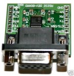
can I confirm are the rx tx vcc gnd in same order on the 6fet board as the 12fet?
pic

pic
philf
1 kW
solarbbq2003 said:can I confirm are the rx tx vcc gnd in same order on the 6fet board as the 12fet?
pic
Yes they are! I flash the 6fet unit exactly the same way that I do the 12, and the pin orientation is identical.
The thing that can bugger you up is the contextualization of "RX" versus "TX". In the picture you've posted, these labels would apply to what the PC expects. "RX" data is connected to "Receive Data" at the PC, and is what the Infineon transmits on. Likewise, "TX" data is PC-relative as well, and is what the Infineon receives on... I had to label that on the picture I'd posted earlier, because I kept second guessing myself on which end of the cable those labels made sense to.

Cheers!
philf
1 kW
I finally got annoyed enough with opening the controllers (or the extra mess of wires I had hanging out of one of them) that I installed low profile jacks in them. These sockets are like PS/2 mouse/keyboard connectors, but have a threaded collar on to which can be screwed a dust cap (which I haven't been able to find yet).
Makes things much tider, and they're only $2.00 each (Canadian)...

Makes things much tider, and they're only $2.00 each (Canadian)...
solarbbq2003
10 kW
- Joined
- Apr 7, 2007
- Messages
- 500
thanks guys for confirming 6 fet board pins
hi
Philf I've just got keywin to send me some controllers of diffrent sizes for testing, using and finding the limmits of.
there are mostly 12fets but some are 9 and one 6 for testing with and an 18 fet for a Team Hybrid customer.
I'll soon be able to have a look at all of what you get up to with these small 6 fets infineons.
Geoff
solarbbq2003
10 kW
- Joined
- Apr 7, 2007
- Messages
- 500
seems the controllers also have an alarm system, no idea on how its works unfortunately!
but a 5 pin connector was supplied on the units I got direct from the board maker for alarm, it uses these pins:
Vcc,gnd, xc, vcc-L and TB
If i can get more info on what it does i will post
but a 5 pin connector was supplied on the units I got direct from the board maker for alarm, it uses these pins:
Vcc,gnd, xc, vcc-L and TB
If i can get more info on what it does i will post
solarbbq2003
10 kW
- Joined
- Apr 7, 2007
- Messages
- 500
SL pin connect gnd-4 is speed limiter
XC is speedometer output signal ( assume its rail voltage constant and amps varies according to rpm to run an analog dial for speed as other controllers speedometer signal seem to work that way)
XC is speedometer output signal ( assume its rail voltage constant and amps varies according to rpm to run an analog dial for speed as other controllers speedometer signal seem to work that way)
Hisolarbbq2003 said:seems the controllers also have an alarm system, no idea on how its works unfortunately!
but a 5 pin connector was supplied on the units I got direct from the board maker for alarm, it uses these pins:
Vcc,gnd, xc, vcc-L and TB
If i can get more info on what it does i will post
I knew there was an alarm on there but had yet to find out where it was connected glad someone else has identified a hole/pad for once TA next to TB is for a pedec system controlled by a latching hall sensor.
Where did the controller come from, post a pic if you can, the lines that have been taped into arethe positive battery line Vcc so if you disconnect the battery from the controller (either with a connector or switch) when you leave your bike then the alarm will not work, the power line to the infineon chip and all assosiated conponents Vcc-L this is prior to any voltage reduction so the same voltage as the battery is at this point when switched on though when off there will be no voltage there, TB is the new one and what that is doing we do not know yet,XC that is connected to phase C through DX on the boards from ecrazyman it is isolated a picture of the board around XC is needed i can gess what to do though there is a colection of 4 holes there XC has 2 toles linked by a common pad and DX has 2 holes linked plus a branch to the phase C control circuitry, looking carfully between DX and XCprinted on the board is a diode symbol so to get XC to work a diode needs to be fitted there why it is not in the first place I do not know. Looking at your board is going to be needed to identify what sort of diode we need to fit.
from your second post
the signal is comein from the phase C circuitry so will probably be frequency.XC is speedometer output signal ( assume its rail voltage constant and amps varies according to rpm to run an analog dial for speed as other controllers speedometer signal seem to work that way)
last also from the second post
SL has been well documented I'm suprised you missed it this is the pad /hole for activating the Speed Limmit setting in the parameter designer setable from 50% to 99% of top speed give top speed is 100% ,the difrence between the SL settings and the 3 speed setting is the way the controller ramps up the speed basicly if you set a speed seting to 50% then you would get a smooth increase in speed as you applied the throttle up to a fixed speed (a percentage not a speed in mph) if on the other4 hand you used the SL switch set also to 50% it would be as if you had the controller set to a speed seting of 100% but when you got to the same speed as you had got to at full throttle with the other setting the controller would clamp the speed increese to that speed giving you in effect about half as much throttle to use when you are on the flat on a slope going uphill you might get more.SL pin connect gnd-4 is speed limiter
the balls in your court now solar run with it.
Geoff
Doctorbass
100 GW
hi doc
the chip used is the XC846 on the 12 fet models this is a starting point though you have done better than most.
I must get one of my trashed boards and trace as many tracks as possable documenting as i go, pin one is next to the small round dint in the chip I presume.
don't do this with a good board I did that and now it has joined the trashed box.
Geoff
Doctorbass
100 GW
geoff57 said:hi doc
the chip used is the XC846 on the 12 fet models this is a starting point though you have done better than most.
I must get one of my trashed boards and trace as many tracks as possable documenting as i go, pin one is next to the small round dint in the chip I presume.
don't do this with a good board I did that and now it has joined the trashed box.
Geoff
ok.. i'll pay attention.. but i still have two board!!.. I ordered one more for tests and debug.. :wink:
Doc
doc that's not what I ment most of us can't find any information on any of the infineon chips, I checked a pic of a 18 fet board I've got it is the XC846 chip but where info on it is none of us know.
your doing well on your 18 fet thread keep up the good work.
Geoff
your doing well on your 18 fet thread keep up the good work.
Geoff
ufa.hujuk
1 µW
- Joined
- Jun 14, 2009
- Messages
- 3
Hello its ufa.hujuk from Germany.Knuckles said:I am sure Keywin can get the red "do-dads" dirt cheap in Hong Kong.
Also made by FDTI I think.
Then just run a 4-PIN JST outside the controller and touch that to the red do-dad.
bada...bing!
I am sorry that my english is non so good. I followed a lot off threads in regards to the infinion controler.
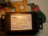
I have a Nine continent front wheel JZ-RH205 and got an 36v 17A controler type is EB806XC-A-12 and it looks very similar to these one in the thread.
I like to put these controller into 3 speed mode with pedelec as it is the regulation in Germany on "roads"
My downloaded Designer-program and the usb to RS232 i prepared as You suggested .
A test of the com line on a second PC RS232 with 9600bd 8bit 1stop no handshake shows when I hit the transmit bottom a grey blinking "Transmit Guage" and on the second PC a series of "88......" but on the EB806 no reaktion.
I started the Transmit and then I connected the EB806 . 5v are simultanous applied by the connector.
Where is my problem ? To get the connection to the second PC I use a zero modem kabel attached to my usb-Rs232 device. Please help
Many thanks
Udo
Reid Welch
1 MW
Hello Udo.
Your English is fine. We, almost none of us, speak more than a word of German.
You are great. Your question needs to be answered, but I have no technical ability to answer your good question.
This post is two things:
WELCOME to our new, German friend
and PLEASE one of you tech experts, help our new pal sort out his problems?
WE are international. We want happy, active members. We want everyone to feel wanted, needed and part of the ebike community
which binds us all together: rich or poor, old, young, American, English, German, Australian, Malaysaian, Chinese.
Broken or accented English is JUST FINE here. We understand you perfectly. You are wanted.
Post often. This is good practice for your English and it helps others here feel involved, useful and appreciated.
Just to post, shy, silent readers, just if you post, "I like what your bike is becoming", is a precious gift to the recipient.
Thanks, Udo!
your virtual new friend in sunny Miami, Florida,
one quarter German-blooded, Reid
ufa.hujuk
1 µW
- Joined
- Jun 14, 2009
- Messages
- 3
 Thanks for Your quick replay.
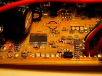
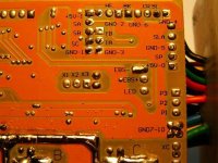
I took a few Pic's of my controller .
At the Rear side there is some contacts described.
I figured some of them out:
SM -- some component's missing ---possibly speed output from MCU
AUX-- one resistor 1,5 k to JZ102 left contact ( ? RX-data?)
VCC-- Batterie 36 V +
JZ102--- ? Programming input? if I compare these thread on EB812 boards
SA--
SB-- 3 lines to the hall sensors of the NC-motor JZ-RH205
SC--
Gnd-1 ...Gnd-10--- Signal ground for different in/outputs
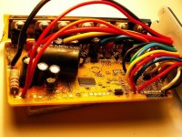
BK-- ?regen break? when switched to Gnd - I put thes line to my right hand break handle "until now no action"
SL-- speed limit when grounded Gnd-4 -- "worked in the original configuration"
EBS-1-- Switched off Pedelec action -- " original attached to the hand break levers " ( left and right)
TA-- signal from PAS ( pedelec sensor ) " startet full support after 3/4 rotation of pedals" I d'ont like this way !!!
SP-- throttel signal ( 1,3 - 4,2 V ) " worked in the original config without pedaling" not to the German trafic rules !
Here the pads , which I d'ont know:
X1 , X2 , X3 , HF , TB , P1 , P2 , P3 , EBS+ , XC , LED , SR
Is there any where a explanation on those contacts ???
The contacts of JZ102 from top and from right I conected to:
RX-data to Rs232 9pol pin 2
TX-data to Rs232 9pol pin 3
middel no conection ? what is this ?
+5v to RS232 9pol pin 9 ( normal RI wired to 5v+ from usb pin 1
Gnd to Rs232 9pol pin 5
Transmit started "no reaction of the program designer , only greyed and blinking Transmit Gauge"
So far my experience with this controller , labled Nine continents 36V, 17A max current
Who can help ?
Best regards and nice biking
Udo
Attachments
hi
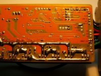
this is a 6 fet controller, please post the pic of the circuit board both sides so i can check against one of the other 6 fet controllers I have a picture of.
do you have the pedlec sensor?
the speed of cut in of the sensor is a problem I have been addressing with Team Hybrid you do have to do two things one is to set the speed settings to a range say speed1=40%, speed 2=70%, speed 3=100% this will depend on legal speed limit and how you like to ride.
First how the pedlec works for us, once you start pedeling the motor cuts in after about one turn or so, the infinneon also uses the 3 speed settins to alter the motor speed so as you pedel faster so the motor goes faster on the surface a good idea, the bad side is this when the motor is running at a speed setting it is at maximum throttle of that speed setting, the othe problem is that the choice of what speed setting to use is TOO close togeter by far since it is activated by a disk with magnets on it one idea is to reduce the number of magnets on the disk (I would start at 4 magnets and go down from there best will probably be 1) this will make the bgike less jumpy.
you also have problems with a throttle being able to start the motor without pedeling you can disable this by just not connecting a throttle it is overrided by the pedelec system anyway If you want a throttle then fit a a switch in the 5v line to the throttle that way you can disable it when you want.
Geoff
Takemehome
1 kW
I just received my FREE kit from E-bikekit. ( One of the five lucky winners )
A 36V 500W 9C with a 9 fets Infineon controller.
If I jump BK to GND, will it regen ? ( without reprogramming it )
In other words, is the default programming set to regen ?
It would be good to know the default settings of the hidden functions.
Maybe some of us don't need to reprogram it at all. Just "Jump and go" :lol:
Label says: Automatic cruise ? ......Is that cruise control or just instant start ?
E-ABS ? ..................Electric Anti-lock Braking System ?
Energy feedback ? ......Probably means regen ?
Mute ? ...................This one, I have no clue.
Okay. My kit is the one from ebikekit.com. 9C motor, Infineon controller, 36v 22a. I installed a jumper from BK to GND. First test was with the wheel off the ground. I got the same results as I did with the GM controller. The brake slowed the wheel for a second, then the wheel kept spinning. Unlike the GM however, there is resistance when spinning the wheel backward, while keeping the brake lever depressed.
Next was a road test. No noticeable regen braking. I'd really like to have the option to stop using regen only. The brake wires are soldered to the board so pulling the brake lever disconnects power to the motor. Also, I noticed there are empty EMS connections on the board. I saw another controller for a different kit, that says it's an EMS controller. Does EMS have anything to do with regen? Two more things, how do I go about adding reverse and cruise control switches?
Next was a road test. No noticeable regen braking. I'd really like to have the option to stop using regen only. The brake wires are soldered to the board so pulling the brake lever disconnects power to the motor. Also, I noticed there are empty EMS connections on the board. I saw another controller for a different kit, that says it's an EMS controller. Does EMS have anything to do with regen? Two more things, how do I go about adding reverse and cruise control switches?
Takemehome
1 kW
edpol said:Okay. My kit is the one from ebikekit.com. 9C motor, Infineon controller, 36v 22a. I installed a jumper from BK to GND. First test was with the wheel off the ground. I got the same results as I did with the GM controller. The brake slowed the wheel for a second, then the wheel kept spinning.
Here is what I found regarding regen:
When you let go the throttle while you brake, the regen is not so great.
Try this: keep some throttle while you brake, you get a good regen back.
Try this: keep some throttle while you brake, you get a good regen back.
Tried that when I first tested. I tried it braking at half throttle, full throttle, no throttle. Results were the same. It turned out to be the LiFePo4 batt doesn't allow regen. It worked great with SLA's, until I installed the switch to get reverse. Now there's no regen, and no reverse. I removed the reverse switch, but still no regen. I don't know where I made the mistake, but I got another controller that has both regen and reverse activated. Turns out to be a GM regen controller, the one they sold before the magic controller. It's also an Infineon, 36v 30a. It should be here shortly.
Similar threads
- Replies
- 3
- Views
- 909
- Replies
- 56
- Views
- 5,291
- Replies
- 7
- Views
- 3,553
- Replies
- 3
- Views
- 4,237