Installing a BMS for Lipo - How to?

majornelson

100 W
Joined
Jun 29, 2013
Messages
277
Location
Bethesda, MD
I'm creating a separate thread for this discussion.

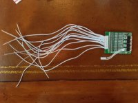
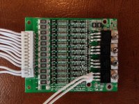
dnmun recently sent me a Bestekpower D122 12S BMS for my 12S 44v 5AH Lipo setup (two 6s Zippy batteries). It looks great- relatively small and will make my battery both safer and more convenient to use and charge.

However, I'm looking for guidance on almost everything... I can solder. ;)

My plan:

1) Determine which sense wire goes where on the battery and then solder.
2) Determine what goes on the 4 poles on the other end of the BMS (I assume it is charge and discharge wires).
3) Install on battery back... not certain what the "best practice" is here. The BMS is small enough to fit on the side of the battery. To date, I have wrapped two of the Zippy 5AH 6s batteries in coraplast and then duct taped them together (makes for a brick like structure). It fits neatly and tightly in my carrying case on the bike. I'd like to continue to use the existing holder.

Once everything is working, I have an on/off switch that I'll attach to the thermal fuse line (recommendation by dnmun). That way I'll be able to shut the battery off without unplugging anything.

I've reposted dnmun comments in the next post and then my follow up questions.
 
dnmun wrote:

there are 13 sense wires. the lowest one is next to the end that says B-. you connect that one to the bottom of the first cell, the bottom of the battery, so they call it B-.

the second sense wire goes to the top of the first cell, the third sense wire goes to the top of the second cell, ...and so on up to the top of #12.

do this before you connect the sense wire plug to the BMS. then after all the cells are soldered to the sense wires, use the voltmeter and verify that each cell is in series, that the voltage steps up by 3.7V or so for each sense wire as you probe the sense wire plug all the way to the top from the bottom. you have to be certain than none of the sense wires has the cell voltage reversed, this is critical. if it is not the BMS will be ruined when you plug in the sense wire plug.

if you peel back the plastic over the end of the 6S pack then there is a white plastic strip that covers the end, and if you don't plan to remove the shrink wrap then you cut across the white plastic piece to expose the top of the cells. then solder directly to the solder on top of each cell to put them in series.

i like to take the shrink wrap and that plastic wrap piece off and put hardboard end plates on each end after i remove that white plastic wrap, then i solder the top of #6 to the bottom of #7 and solder the sense wires to the top of the cells. i removed the JST plugs on these packs.
 
majornelson wrote:
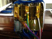
I get the idea... of course, my Zippy looks a little different. I've a attached a picture of my battery end and labeled where I think that I would start and so on (is this correct?). I'm confused by the count. There are 11 white sense wires on the board plus two more in a smaller connector. I count 7 places to solder on one battery, which with two batteries would equal 14. I'm guessing that a battery contact is bridged and uses only one sense wire.
Lipo Battery for BMS.jpg
 
the little DIP switch can be installed in one of the wires that goes to the thermal breaker. when you turn the switch off it will interrupt the circuit current that controls the mosfets so the BMS will turn off the battery and it will not spark when you connect to the controller and it will not short out on stuff when you handle it or carry it in a knapsack to class.

where you have the #1, that is the bottom of the pack for the 6S. when you connect the two 6S in series to make the 12S, you should first take the two 6S pack out of the shrink wrap and then put them end to end, put some end plates on and compress it modestly with some wood clamps and then wrap with duck tape to hold the two 6S together into one 12S.

under the yellow kapton tape over each terminal of the cells is the soldered rib that connects the cells sequentially. you solder to that.

the black 12G silicone wire at #1 is gonna connect to the B- spot of the BMS. so you cut that wire long enuff to reach the BMS where you locate it, and save the bullet end to use later to connect the pack to the controller. on the other end, you cut off the red wire at #7, cut off the black wire at #1 of the second pack next to it and then solder a jumper wire that connects the top of the first pack to the bottom of the second where those two wires are soldered down. save the two wires you cut off to use later for wiring the pack to the bike. leave the red wire at the top of the second pack intact because that is where you will connect the battery to the controller. using the cut off black wire from #1. they mate.

the sense wires then go in order from your #1, where you would solder the first sense wire, up to the red wire, #7 at the top of the second pack on channel #12.

disconnect the sense wire plug when you do this and you wanna verify the voltages on the sense wire plug are in order sequentially from #1 to #12.

you can leave the JST plugs on each 6S if you wanna and then you can plug in the cellogs to measure voltage that way. but you solder to the same place where the JST sense wires are soldered. when you solder the 7th sense wire, you solder it to the jumper wire, i use 12G solid, that bridges the two packs.

hope that makes sense, i am gonna build up some 14S lipos so maybe i will work on that today and post up pictures yet. but you can see how i build them from my picture. i think the hardboard end plates are needed to protect the pouches when you drop them and they keep the compression uniformly distributed over the entire surface of the electrodes inside the pouches.
 
finally finished that pack, i split the shrink wrap and removed the tape, cut off the sense wires and then the terminal cables on one or the other of two and then cut them both off one of the 6S so i could take it apart. unsoldered it into three 2S sections which allows me to insert the 2S section into the middle of a 12S to make 14S with the tabs lining up in the right place to resolder it into one 14S piece. you can see in that picture before the tabs are soldered to each other in the middle to complete the series.

then i soldered the sense wires for the new BMS on, cut the B- cable and soldered it to the BMS and use the stump to make the P- connection to the battery. and i added the DIP switch to the thermal breaker. i have enuff parts to make 3 of these 14S packs with these BMSs. the neat thing is that it charges to 58.8V which is the exact output voltage of the 48V headway charger i have. and eventually this pack will be part of an experimental16S lifepo4/14S lipo hybrid.

i really want to establish this as a tiny little cheap simple to build 14S pack to use with an old and tired 48V ping in parallel. the 6S turnigy were $43 each, so $100 for the lipo, $25 for the BMS. $1 for solder, $400 labor. 2 hours.
 

Attachments

  • DSC01702.JPG
    DSC01702.JPG
    68.2 KB · Views: 12,804
  • DSC01703.JPG
    DSC01703.JPG
    55.9 KB · Views: 12,803
  • DSC01706.JPG
    DSC01706.JPG
    42.4 KB · Views: 12,803
  • DSC01707.JPG
    DSC01707.JPG
    63.3 KB · Views: 12,803
  • DSC01708.JPG
    DSC01708.JPG
    77.2 KB · Views: 12,803
  • DSC01709.JPG
    DSC01709.JPG
    84.2 KB · Views: 12,803
  • DSC01710.JPG
    DSC01710.JPG
    69.9 KB · Views: 12,803
  • DSC01712.JPG
    DSC01712.JPG
    77.1 KB · Views: 12,806
The master at work. Off to link this thread in the Battery FAQ's
 
maybe i shoulda put this D126 build in the Bestechpower BMS thread.

he got a different one from me. it is the D122 which is maxed out at 12S and is tiny tiny. we don't know how much power it can handle but it has some big mosfets, irfb3607 (70A each) so i think it should be able to handle up to 30A but it is rated at 15A continuous.
 
These type of cells should be monitored closely while being charged and should be charged with a good quality rc lipo battery balance charger.

If you do not know how to use a good rc balance charger then you should not be trying to charge these types of rc lipo cells.

Counting on a low cost bms to take charge of the charging is not a good way to go with hk lipo.
 
you know nothing. you have no right to insult other people just because you are ignorant of how a BMS works. just get off this thread and go start your own thread if you ever figure out how they work and can find some flaw in their use. leave this guy alone.
 
I know how they work and know how they fail.

I know about how quality rc balance chargers fail sometimes too.

HK lipo is very prone to exploding if overcharged and should be monitored closley while being charged.

A good rc charger helps to monitor closely.

The good news is that rc lipo can be charged fast with a good rc charger.

That way you don't have to sit by it very long. :)
 
etriker said:
These type of cells should be monitored closely while being charged and should be charged with a good quality rc lipo battery balance charger.

If you do not know how to use a good rc balance charger then you should not be trying to charge these types of rc lipo cells.

Counting on a low cost bms to take charge of the charging is not a good way to go with hk lipo.

Do you believe the balance circuitry within the charger is any different from the balance circuitry within a bms?
Your advising that the most potent chemistry be run without bms, and instead charged as if it was a model plane or something. Like in the fire threads?

I don't understand what you are saying. It seems nonsense. As the most dangerous chemistry it demands the most respect. Some people seem to think as it's the cheapest chemistry they should cut corners. I have heard others say there is no point using a bms with rc lipo, and even that nobody does. That is how common it is to do things wrong. There is no justification for it though. It actually seems like total lunacy to me.


I see you have posted some more as I typed. The only point you make beyond hearsay is that you would rather have just one over voltage control than two. Lunacy I tell thee...
 
The best way I know of to monitor a pack while charging is with a Hyperion hooked to a display.

That gives the most feedback about what is going on.

BMS gives little feedback.

If you do not understand what is on the Hyperion display then it is noise to you ?

I am thinking if you can not understand what is on that display you should be using a cell type that is less prone to explode.

HK does sell alot of rc chargers and alarms and tools to closely monitor the rc lipo cells when charging.

Not a lot of BMSs.

(all ebike packs should be able to easily connect to a cell log)
 
This is clearly - "How to?" not "help me decide?" thread. The choice has been made, if you can help the man, help the man. If you only wish to take "pot-shots" and clutter-up the OP question, well then....
 
majornelson said:
12S 44v 5AH Lipo setup (two 6s Zippy batteries).

What batteries did you actually get?

I ask because all the one's I have seen come with balance wires that just plug in to the bms. I don't understand what all these white balance wires are for if you bought RC packs. I know the wires come with the bms, but mine went in the bin. The wire's were already on my batteries. I did not build from cells like in the pics dnmun is showing. I used packs like I thought you got.
 
This is exacly what I am going to do. A 10s or 13s 5ah pack is what I am leaning towards. Thx for the thread dude! :D
 
A typical 6 fet controller, adequate for a 15 amp bms, won't like 13s lipo. You can mod the controllers, but they're typically used 12s instead. It's an issue of voltage rating, with regards to just a few capacitors I believe. It is also wise to mod part of it's own internal power regulation to. Just a resistor swap though.

Many peripherals have led battery meters that expect 36v or 48v not a 44v 12s pack. The power level lights would lie to you.

Edit: The cheapest 12s 5ah lipo I have seen is $69 from HK. It is three 4s packs, and they are hard cased.
 
First, dnmun, thanks for the great write-up, photos AND the BMS. Outstanding! As I work through this, I'll post any additional questions or clarifications (from a beginners perspective!).

A couple of quick questions for those following this thread:

1) How important is it to compress and surround by wood? I think dogman had posted something about using coraplast, which is what I've currently used, to protect the batteries. And then my battery pack is placed inside a small wooden box where it is protected but it is not compressed except with the shrink wrap. Basically, I'm tight on space.
2) Can the BMS be attached/taped/glued to the battery or does it need to go someplace else?
3) friendly1uk - I have Zippy 6s (times two) 5Ah Lipo from HK. I do have the balance wires. Not certain why they could or couldn't be used (instead of soldering new ones).
Here is the link to the battery: http://www.hobbyking.com/hobbyking/store/uh_viewItem.asp?idProduct=16706.
4) I have an iCharger 306B. Is it correct that I would connect this to the BMS and not bother with a balance charge as the BMS handles it?

Finally, on the BMS is a hole next to B-. From dnmun's pictures, it looks like the negative battery cable from the first pack is soldered here. The other hole labeled P- looks to be the negative to the controller. And from the above posts the positive from the last battery pack goes to the controller. All makes sense. Just don't know where the charging cables go unless it is the same wires. In this case, can I split them so I can have install a built-in charging port on my wooden box and also have the battery hooked up to the controller? (This is the way my battery pack from cellman works and it is very convenient.)

I'll post pictures as I complete this project. Both to help others *and* to make certain I'm executing it correctly.

Lee
 
i don't leave those JST plugs on because i intended to make a 14S pack and so if i wanted to have cellogs on the 14S then i would use two sets of 8 pin JST plugs to handle 7S on each cellog.

the B- is where the negative battery lead is soldered, P- goes to the controller, and the C- spot is where you solder the negative charging lead. the red positive charging wire goes directly to the top of the battery B+ where the red wire comes off. solder the red wire from the charger there if you use a different wire for charging.

i use the 1/8" hardboard because it is stiff enuff to support the compression with the clamps, coroplast is not stiff enuff. also it is free to me because i got a bunch for free. i have used 1/4" plywood too on my ping 48V20Ah rebuild, but that was overkill and i use the 1/8" hardboard all the time now.

the sense wires are easy. like i said, start with the lowest sense wire and put it on the bottom of the cell #1. the second wire goes to the top of #1 and then sequentially up from there to the top of the pack. it is obvious once you start working on it, but do verify the voltages on the sense wire plug before you plug it into the BMS because you can get them out of order and if you plug it in with the voltage reversed on one channel it will ruin the BMS.

i would never use the small wires that come with the turnigy pack to charge because there has already been a fire caused by shorting of those balance wires. if they short while charging the amount of heat released is significant because not only is the charging current shorting out but the entire cell is now shorted through those balance leads and as the insulation melts on one of those tiny wires it shorts out to the next cell or one several cells up so the shorting cascades into a thermal event that cannot be controlled and is not detected by the charger which cannot stop it in any case. this is what they don't tell you when they tell you to use balance chargers.

i am gonna go post these pictures in my bestechpower BMS thread along with some pictures of the other BMSs i bot from them. also i will review what i have done so far to test my 14S pack with the D126 BMS.
 
I am a newbie but have been doing a fair bit of reading on this site over the last month.

I'm building an ebike now and am looking to go down a similar path (2 x 6S 5000mah lipo packs) to give me 12S - 44.4V nominal, just like the OP.

I've bought a balance charger to charge them, but very much like the idea of implementing a BMS to make the charging procedure easier and quicker, again just like the OP.

There are the obvious charging limits for LiPo (never over 4.2, never under 2.7) but from what I've read the ideal charging range is more along the lines of: not above 4.1 and not below 3.65 (in order be conservative and prolong battery life)

I just had a look at the specs for the Bestekpower D122 12S BMS on their website and it looks to me like the overcharge detection range is between 4.2V and 4.35V and that the overdischarge detection range is between 2.3V and 3.0V.

So, neither the overcharge nor the overdischarge ranges allow me to implement the ideal range with in particular the low range being a long way off from ideal?

Have I got this wrong? (in a way I sorta hope so, because I'd like to use a BMS as well.)
 
Back
Top