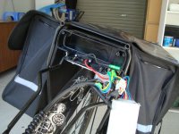
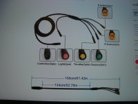
That first picture is a 9 pin cable, yes. Unfortunately, it has nothing to do with motors. It's for connecting a controller to various accessories like throttle, brake sensor, lights, display, etc.. Generally every wire in a cable like that is the same thickness.
There are 9 pin cables that connect from a controller to a motor, but they are quite different. The motor cable has 3 very high current lines called the phase lines. These are the three lines the controller sends more power to in a repeating cycle when the throttle is high. They are generally larger and thicker in the motor cable connector to handle all the current without overheating. The motor cable can also have wires for the power and ground to the hall sensors, signal wires for the three hall sensors, optionally another signal wire for an rpm/speed hall sensor, and optionally a wire for a temperature sensor.
If you check the Grin site, you can see a cross section of a 9 pin motor cable:
View attachment 339925
There are lots and lots of connector types used in the ebike industry, so many that it would be a very tall order to try and list them all. In our business, we focus just on aftermarket conversion kits and have tried to keep the connector styles down to a well chosen minimal set. This page...

ebikes.ca
Note it doesn't have a pin for throttle since throttle goes between the controller and the throttle, not between the throttle and the motor.

.png")