JD's BMC V3 Build - in progress

oatnet

1 MW
Joined
Apr 26, 2007
Messages
2,360
Location
SoCal, USA
I just got my BMC V3 motor from Ilia aka ebikes_sf for a good price, :D without the ridiculous markups I have come to associate with other vendors BMC products. I've been wanting to build one of these 1000w motors since I first saw a youtube of one advertised as the 'black lightening'. I have heard impressive reports of speed, torque, and effeciency at low voltages (like 33mph@36v :shock: ), and I look forward to discovering that for myself. Then I look forward to pushing those limits, maybe as far as 120v with a Kelly Controller.

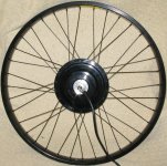
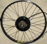
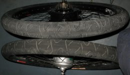
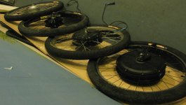
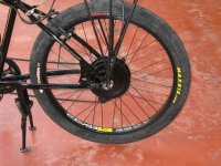
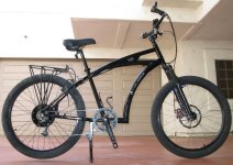
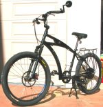
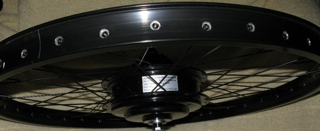
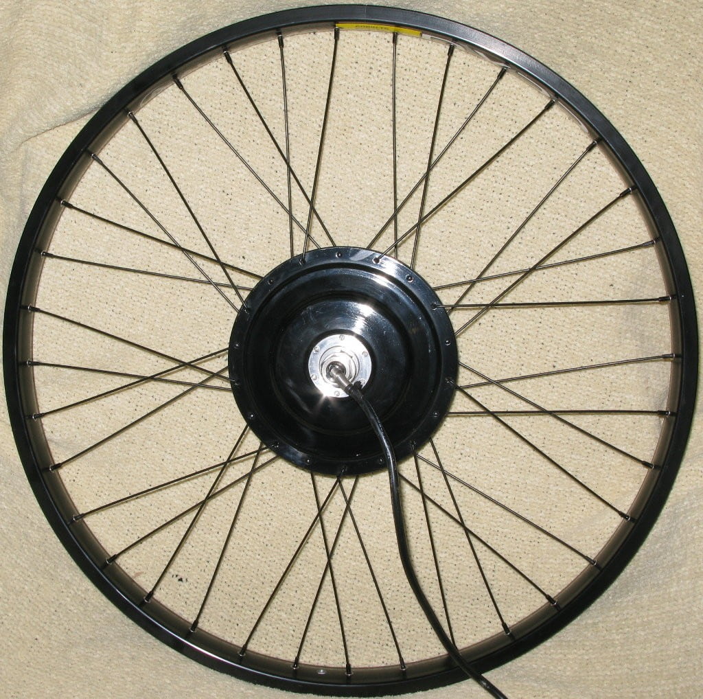
As a carryover from my ICE days, I am a big believer in stealth. Big loud motors attract attention, which is fine for show, but not so much when you want to push the limits. This compact motor should help with stealth, and I hope it is not too much noisier than hub motors. It comes in gloss black, and I have a spare gloss black Tidalforce IO Cruiser frame, so I decided to go for a 'blackout' bike, trying to make everything possible gloss black. I also wanted a WIDE rim, to put the best possible patch on the ground, and make the most of the 2.5" Maxxis Hookworms that have become my standard. Ilya suggested the Alex DX32 downhill rim, a whopping 39mm wide, a bit heavy for some downhillers but built like a tank making it a great choice for ebikes. In the pics below, the flash makes some of the gloss black spokes look silver, but they are black.

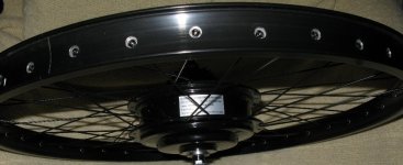
I have a few questions for wheel-builders. Ilia is just lacing wheels to help people out, he isn't a full-time wheel builder. I noticed that he missed the 'key' spoke and the spokes 'V' right where the air valve hits, instead of being open for easy access. I also noticed that onh all of my other hub motors, where the spokes cross they are bent over each other, and I thought that had something to do with distrbuting tension and making the wheel stronger. In this case, the spokes are not bent over each other at the cross, there is actually a gap between them. Given that I intend to subject this motor to some pretty heavy stresses, should I re-lace the wheel so that the spokes cross? If I do so, will I need longer spokes?

label_7737.JPG

file.php


file.php


file.php


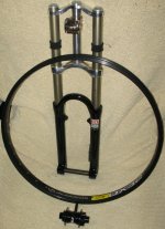
I wanted to match the front wheel to the rear wheel, so Ilia supplied me with another Alex DX32 rim. I like the Rock Shox Boxxer fork I used on my xtracycle, so I bought another one used on ebay, with black lowers. It was cheap but It needs a rebuild, and I think I will pirate the black crowns from the xtracycle to keep to the blackout theme (anyone know where I can source a cheap uncut steerer tube/crown for Boxxers?). Since the Boxxer uses a 20mm-through-axle wheel, I sourced a 20mmAdventure Components Aircooler hub to complete the picture. Now I just need gloss black spokes, and to rebuild the fork, and I'll have a front end.

[img]http://endless-sphere.com/forums/download/file.php?id=26085

For the meantime, I'm going to use the stock forks and experiment with this motor to see what it can do. I'll grab one of my spare 72v LiFe packs and use it to test these controllers with the hub - a generic Crystalyte 72v25a analog controller to start. This should supply close to 2kw to the this 1kw motor, and we'll see what's what.

Then I'll try one of the 'knuckles' 72v50a infineons I have had sitting around, and see how it handles 4kw. I read some folks were having problems with these heating up on V3s, and I wonder if it was just the resistance head from the phase wires. I'll clip the skinny OEM phase wires on the motor as short as I dare, and solder on some 8gau leads instead. I'll still have the measly 14gau wires going into the hub, but they will be a very short run, and I hope the 8gau will help bleed off some of the heat from them.

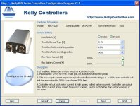
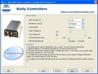
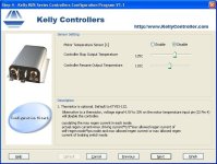
If the motor still feels strong, and the frame feels like it is handling it well, and I am feeling daring, I'll move on to the Kelly, and maybe up to 120v. I might recruit an experienced motorcycle rider with protective gear and a full-face helmet to volunteer for 120v test runs. I am very curious to see what this motor can do at 120v, but 45mph made me nervous and this promises to go much faster.

file.php


-JD

Please forgive the shrunken pics that get stuck at the end:
 

Attachments

  • disk side_7734.JPG
    disk side_7734.JPG
    232.8 KB · Views: 9,334
  • cluster side_7735.JPG
    cluster side_7735.JPG
    215.7 KB · Views: 9,332
  • top_7736.JPG
    top_7736.JPG
    61.1 KB · Views: 3,870
  • front Assembly_7740.JPG
    front Assembly_7740.JPG
    254.1 KB · Views: 9,319
nicobie said:
I like the idea of a triple clamp fork and have been looking for one for my Townie. Now I know who has been buying them out from under me on the bay. :mrgreen:

:p - If you find one you want me to leave alone, send me a PM. :D

Yeah, I need a long steerer tube too. I think the uncut one I have on the xtracycle might be close on the Tidalforce IO frame I am using - I need 8.5" just to clear the the upper clamp on that one!

-JD
 
I decided I have lots of radial-spoked hub motors, and since the spokes don't tension against each other on those and I haven't broken one yet, I'd go ahead and mount the tire. Hookworms can be a bitch to mount sometimes, requiring a little KY to slip that last bit over the rim, but I managed to clear this one over the rim dry without too much effort. Although the lacing left the air valve in a less convenient place, I have to say that it didn't really give me a problem when filling the tire, so I don't think it is a big deal.

As the pictures below show, the BMC V3 with a 7-speed cluster mounted on an Alex DX-32 Rim weighs 12.8 lbs.
WIth the Maxxis Hookworm, Kenda DH 2.25mm thick tube, pendaflex liner, rim tape, and 65lbs air pressure, it weighs 17.0 lbs.
An 8fun (aka Bafang) on a Rhyno Lyte with the same tire setup weights 13.8lbs, so the V3 and DX32 upgrade is a mere 3.2lb weight penalty. Of course, the BMC is also more than double the cost, and the larger diameter is somewhat less stealthy, but it is still a small motor. :D

-JD

IMG_0241.jpg

IMG_0242.jpg

IMG_0243.jpg
 
Allright, some more ebike Pron for you.

I had some loose hub motors sitting around, mounted with the only tire combo I use (Maxxis Hookworm, Kenda 2.25mm thick downhill tube, Pendaflex Kevlar liner - tire and liner learned from one and only xyster [we miss you man! wish you would come back!]). I thought it would be fun to line them up so folks could get a sense of their realative sizes. The 26" mounted motors are:

Tidalforce DD
Crystalyte 5305 DD (aka Phoenix Brute)
BMC V3 geared (subject of this thread)
Bafang aka 8fun geared

But, before we get to the comparison shots, I wanted to show a photo comparing the hookworm tire in a 29mm Rhino Lyte rim vs a 39mm Alex DX 32 rim. On a 39mm rim, the tire is 4mm wider, but that means overall diameter is 4mm larger - I hope you can see in the photo below the difference, it is a stunning in person, the contact patch is much larger.

-JD

file.php


file.php


file.php


file.php


Now, for the weenie sized version of the pics:
 

Attachments

  • wider_7764.JPG
    wider_7764.JPG
    96.5 KB · Views: 3,729
  • 8fun-v3-5305-TF_7758.JPG
    8fun-v3-5305-TF_7758.JPG
    282.4 KB · Views: 9,151
voicecoils said:
I'm really looking forward to a X5 vs BMC V3 1000W comparison.

Keep us up to date! :D

Sorry, I haven't been able to get back to ebikes all week, but I hope to have it running in temporary fashion today. To whet your appetite, here is a someone elses vid of a 600w BMC vs a 5304 - the BMC wins, I expect the 1000w will do even better.

[youtube]nGoLMGPPwow[/youtube]
 
Well, a frustrating day. I did a bunch of research here to see what hall connector connections other folks were using on their BMCs. Ilia (who I bought the motor from) had posted an unusual configuration that had the BMC blue wire connected to the controller black wire. I have seen the phase wires in all sorts of combinations, but I have never seen red and black hooked to anything but red and black. After looking at everyone else's configurations (and extrapolating a BMC 600w-infineon connection), I came up with this:

BMC Halls.JPG

So I went down and started hooking it up. I had asked Ilia to leave the hall connector off, and just send me one of the flat 5-pin connectors that Justin of Ebikes.ca uses, and I'll hook it up. Boy, am I glad I did - before I started I tried a continuity test of the connector (I'm anal about that sort of thing), and got nothing. I stripped back the shrink wrap, and discovered that the pins are mounted exactly reverse from the bikes.ca diagram below, as if Ilia had the connector flipped upside down when he inserted the pins. Well, at least 'green' is correct. I'd simple reverse the pins to fix it, but they are epoxied in place, as if that would waterproof it. Too bad, as the blue pin is not fully inserted, and I can't move it. Edit: Ilia promptly PM'd me back (and for some reason I missed it) and reported that those pinouts are the as-shipped BMC wiring standard - which it would figure :roll: is the exact opposite of what ebikes.ca decided to use.

View attachment 4

So, I write myself up another color diagram (red to black, black to red etc) and hook up the hall sensors as detailed above. Hook it up to a controller, with the motor phases as listed above, nothing, zippo. Disconnect the CA, zippo. Try a different controller, zippo. Hook up a different hub motor, motion. Plug the BMC back in, zippo. Rip off the hall sensor connector, redo a connectivity test on the wires, and some of them may be sketchy, and there is that problem with the blue pin... So I figure either I have the wiring wrong, or it's either a bad hall connector, or (unlikely) the motor is flat dead. I'll make a new hall connector when I have a spot of free time again, but can anyone else with a BMC V3 1000w (or BMC 600w) validate my hall/phase wiring?

Anyhow, I took a few moments to take the blackout bike outside for a few pics. I look forward to completing the look with Rock Shox Boxxer double-crown forks on the front, and the 20mm axle front wheel, not to mention cleaning it up a bit, but here it is:

-JD

file.php


file.php


file.php


file.php
 

Attachments

  • motor mounted_7808.JPG
    motor mounted_7808.JPG
    171 KB · Views: 3,554
  • right_7802.JPG
    right_7802.JPG
    125.9 KB · Views: 3,535
  • front_7781.JPG
    front_7781.JPG
    166.2 KB · Views: 3,525
I think I have an answer.

I found an old 5-pin hall sensor lead laying around because I had done a bad job on it and chopped it off. It looks like ebikes.ca has a different standard now. I poke around on their site, and found the ORIGINAL configuration they used on 5-pins.

Here is the OLD connector:
Rectangular-5-Pin-Connector.gif

Here is the NEW connector:
Hall_Connectors.gif

I get really, really frustrated when Vendors change pinouts without changing the connector. :twisted: I wonder how many folks are going to plug new controllers into old motors and find they don't work. Still love ya Justin, you are one of the good guys, but oy.

DagNabIt.
-JD

Edit:

And for good measure, Ilia's mapping of BMC to Kelly, showing BMC's 'standard' for the same connector, which is naturally exactly opposite ebikes.ca's 'New' standard:
file.php
 
Yep, that fixed it. I have motion with my secondary xlyte 72v20a controller, but it is too late to go out and enjoy a ride. :cry: Maybe next weekend.

My primary 72v20a controller lights up, and shows up fine on the CA, but doesn't do squat. Maybe it got toasted from the bad wiring, maybe I messed something up when I installed the CA connector a few weeks ago. I'll have to take it apart again to see if something came loose.

Well, at least I have motion!

-JD
 
Thanks JD for posting the wiring. I will be doing mine soon, after I get the wheel dished correctly. Can't wait to see how your motor performs. That was the motor I originally wanted but went with the 600watt version.

Do you have a revised color chart for the final wiring you can post or did I miss something?
 
kfong said:
Thanks JD for posting the wiring. I will be doing mine soon, after I get the wheel dished correctly. Can't wait to see how your motor performs. That was the motor I originally wanted but went with the 600watt version.

Do you have a revised color chart for the final wiring you can post or did I miss something?

I look forward to seeing it, Kin!

The wiring chart above is the one I used, I think the colors are correct - I just had the controllers' pins mapped to the wrong wrong colors. I haven't had time to give it a street run yet - I started welding class at a local community college's night school this week, so I have even less time than usual. :D Hopefully over the Holiday I can carve out some time to get it on the road.

-JD

file.php
 
Hey what a cool idea. I might look into a welding class as well. I wonder if they let you build your own stuff?
 
kfong said:
Hey what a cool idea. I might look into a welding class as well. I wonder if they let you build your own stuff?

I think it depends on your instructor. I have a long way to go before I am good enough, but it is a lot of fun learning about working with metal. Although the course is really dedicated to stick welding (SMAW), we will get to play with tig and oxy-acetelene. We just got schooled on a cutting torch... First time I did poorly, and people were lined up to try it. This time I got to go off on my own and I spent over half the lab period cutting 1/4" strips off a metal plate until I got a feel for it. It is amazing to see a stream of oxygen cutting through 1/2" steel plate like warm butter.

Anyhow, got my Kelly KBS72121 controller specifically built for the BMC V3 motor. I really appreciated the fact that they supplied matching plugs and pins for all of their connections - saves hacking up their cables. But the big thing for me is the size. You can see below the Kelly Controller I had originally planned to use with the BMC... If this new controller offers Kelly Reliability in a small package, I am sold. Now if I can just get them to start adding cyclanalyst connectors... For the meantime I'll have to move one of my external-shunt cycleanalysts over to it so I can see the battery-side draw and get some wh/m calculations.

Hopefully this weekend I will get some time to set it up. Since this is a Kelly, I can also adapt a Tidalforce thumb throttle (my favorite throttle) instead of the xlyte twist throttle I currently have mounted on the bike, and we'll see how this 1000w BMC rides at 72v50a!

-JD

kelly on kelly action_7918.JPG

kelly on kelly 2_7919.JPG

kelly on infineon_7921.JPG
 
That's looking great! 8)

which Infineon is that one, a 72v45A 12fet version? Trying to gauge size...

I'm really holding out on your results. I'm ready to pull the trigger on a BMC. Either the V2-S or the V3 now that Kelly's got a controller set up for it.

Will you be able to try the V3 on 48v of lifepo4 too?

Any idea what the weight difference is between the V3 and V2 (bare motor)? I've been looking around for weights and haven't seen them :? .
 
Wow, I like the new smaller Kelly controller. The size of the original Kelly was one of the reasons I was turned off on the 1000w version. Would be interested in how efficient the 1000w compares to the 600w version.
 
Wow, how disappointing. Planned to work on the bike today, got called into work. Got everything sorted there, came home and thought I'd try to program it.

Downloaded the KBS programming app, hooked up my switch box, fuse, and battery to the Kelly, and tried to program it. I got the 'Can't connect to controller' message. Hmm. Check everything over, make sure I am getting power, and try again a few times, nothing.

Hook up the throttle, hall (had to reconfigure to kelly standard), and xlyte throttle (hope it's right, none of the colors match the manual). Nothing.

Check the fuse again, then just take it out of the loop, nothing. Take my switch box out of the loop, get a big snap when I plug it in (so I know it is getting power), nothing. Move the whole power setup to the xtracycle, it powers up fine, and the programming app for that one works like a champ.

So it looks like a DOA. There are days when this hobby sucks A$$.

-JD
 
Make sure you have both power inputs - the main power for the motor and the second power for the processor. You cant program it with just the main power for the motor. I have not tried it, but I bet you dont need motor power at all to program it.
 
dirtdad said:
Make sure you have both power inputs - the main power for the motor and the second power for the processor. You cant program it with just the main power for the motor. I have not tried it, but I bet you dont need motor power at all to program it.

(smacks self in forhead)

Thanks DD - I think you are right! Thanks for the advice!

I am used to hooking up that secondary power line when soldering up the J1/J2 connectors on the bigger ones, but with this little pre-wired one, I went into normal-ebike-controller mode and skipped over that bit. I'd check it now but I have half-quaffed my frustration martini and don't want to go mucking about now.

So I'd guess in theory this would have no power drain when the logic is turned off... Maybe I'll skip making a power switch box for this one, and just use a little switch for the logic side. I noticed they shipped the typical big-resistor/diode in the packet (the other reason for building the power box), but the wiring diagram doesn't show them on the main contactor, so...

-JD
 
That is right about the power switch and power drain. Infineons are the same way. Because of the low amperage switch option you could easily run the switch all the way to the handlebar as a kill switch, which is a legal requirement in some locations. I think any ctlr with a power switch probably works this way. Another nice thing about that kind of power switch, when you are also using a cycle analyst direct connect, is that it shuts down the CA and its display at the same time. Bummer that the Kelly does not yet have a CA connector, I am just sayin....
 
Yep, dirtdad was right (thanks DD!). I pulled the pin for the pink wire from the connecter, jammed it into the anderson, and was able to program the controller. High pedal-disable kept me from getting it working immediately, the default of 10% for the low throttle position was too low for both the xylte throttles I tried, I set it to 20% and that works. I'll solder up the hall conector, and give it a test ride; oh, for the halls connector and phase wires the connectors are color matched all the way through, yellow to yellow etc.

Next I need to move an external-shunt CA to the bike so I can see what it is doing, wire up a Tidalforce Thumb throttle, build a switch box to handle both main and logic power, mount the controller, and I'll have a basic setup for testing.

-JD

PS Here are the settings I am using for the Kelly right now (note the picture on the User Program does not match the controller!):
 

Attachments

  • 1.JPG
    1.JPG
    63.7 KB · Views: 6,669
  • 2.JPG
    2.JPG
    65.2 KB · Views: 6,665
  • 4.JPG
    4.JPG
    55 KB · Views: 6,666
One step forward, two steps back. I've built dozens of ebikes, it just shouldn't be this much of a challange :twisted:

Long story short, I took it out on the street, and even at 72v it doesnt' have enough torque to move me up my driveway. It pedals just fine, and I can do an 8' circle in my driveway at 2-3mph. Since I can't hook a cycleanalyst up to it, I can't see what's going on with the current, but I'm working on that.

This is the same behaviour I saw when I was testing with xylte controllers, but they had even less energy, and then even that would cut out in 10 seconds. When I ordered the BMC-V3 specific Kelly controller, I stopped testing the xyltes.

The halls and phase wires are mapped color-to-color, so that should be right. I tried (2) throttles so I don't think that's it. I verified I am getting 80+v from the LiFe pack I am testing with, and it doesn't have a BMS so it should pull all the amps it wants. My Kelly settings are exactly as above. Dirtdad, any more miracle ideas?

-JD
 
In my testing I got unexciting results, less than 25mph @48V and 24A. That all the amps I can expect from my battery's bms, though. That is not enough amperage to extract good performance from the V3. The cycle analyst seems to be the right next step. See how many amps you are actually pulling.
 
dirtdad said:
In my testing I got unexciting results, less than 25mph @48V and 24A. That all the amps I can expect from my battery's bms, though. That is not enough amperage to extract good performance from the V3. The cycle analyst seems to be the right next step. See how many amps you are actually pulling.

Heck, I would have been more excited getting 25mph at 72v than I am now. :lol:

Well, I really didn't want to take off the Direct-Connect Cycleanalyst I have already installed on the BMC bike during xlyte controller testing. I also didn't really want to remove one of my 'standalone' Cycleanalysts from the bikes they are on. There is one Tidalforce with a 'standalone" CycleAnalyst, the cable to the shunt is poorly mounted, I was going to cut it so I could run the wire through a channel in the frame (the shunt is too big to fit). So I could remove it easlity later, I was just going to put a connector on both ends of the cut.

Just now I thought heck, if I use a standard CA-6-wire connector, and wire the 4 wires the same way the CA-Direct Connect is wired, I should be able to hook that shunt up to ANY CycleAnalyst. So I am gonna go do that now. When I cut the cable, I see Blue, Blue-Striped, Orange, and Orange-Striped wires. These are the same colors I got on the High-Current CA I used on my VW Bus conversion:

CA_wiring_HC.JPG


Since pins 2 and 3 both go to the same place, I can put blue and blue-striped on either one, like so:

CA connector <--> Shunt Wiring
1) Vbatt (red) <--> Orange
2) D gnd (black) <--> Blue-Striped
3) A gnd (blue) <--> Blue
4) Isense (white) <--> Orange Striped
5) Hall (yellow) <--> NULL
6) Ebrake (green) <--> NULL

Wow, if Justin wired the standalone CA this way (6 wires on the CA side, 4 wires on the shunt side), you could unplug the shunt and use it as a direct-connect CA too :shock: , sort of a Universal CA. If he offered the shunt as an optional plug-in, then he would only need to sell two versions, one with the speedo cable and one without.

After installing CA connectors on a variety of controllers over the years, and playing 'hunt-for-a-hall-output' too many times, I always opt for the external speedo cable these days.

-JD
 
Back
Top