JK BMS Issues

cjorgensenmd

10 µW
Joined
Oct 11, 2022
Messages
6
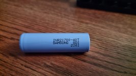
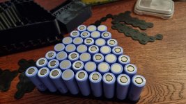
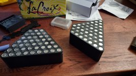
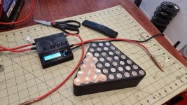
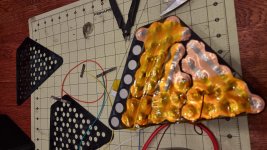
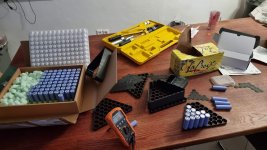
A few months ago I built a 14s6p battery pack from Samsung INR21700-40T cells.
20220713_171011.jpg
20220713_171110.jpg
20220713_172020.jpg
20220713_173608.jpg
20220713_175435.jpg
20220713_195401.jpg
20220713_212950.jpg
20220717_161408.jpg
20220717_161412.jpg
20220720_214054.jpg
20220720_214100.jpg
20220720_215142.jpg
20220721_230821.jpg
20220721_230828.jpg
20220722_184424.jpg
20220723_124033.jpg
20220723_124048.jpg
20220723_160833.jpg
20220723_174324.jpg
20220723_212316.jpg
20220723_224546.jpg
20220726_213711.jpg

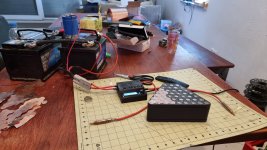
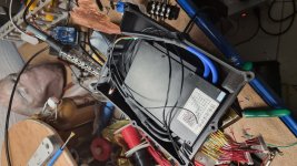
I recently took the top case off in order to install a new top with a VESC and 48v->12v converter. Everything was going great until I connected a voltage display. It should not have shown anything with the battery turned off, but instead it showed 26v.

I turned the battery on and connected the horrible JK BMS App. It showed most cells at or below 2v with one cell grouping not registering at all.

I am currently trying to resurrect my battery by removing the BMS and top balance charging each parallel group individually. My theory is the BMS did not actually turn off the output when I switched it off. It similarly failed to switch off the output when it got to the low voltage threshold. Has anyone else faced a similar issue with this BMS? It was fairly expensive and highly rated, so I did not expect to face this kind of an issue.

Also, any tips on resurrecting the battery? Right now I am just slowly charging each parallel group.
 
There's a bit of prior data missing. What were the batteries doing, or what were you doing with them? You say you turned the battery on and off; by what method? Before or after connecting to the bms?

You said the BMS did not turn off the output when you switched it off, or when it got to low voltage threshold. Not sure what you mean by that. Have you ridden the bike successfully through a full charge/discharge cycles, or is this the first time you've used this pack? I'm wondering, if you say the bms failed to cutoff at low voltage, were you riding it all the way until the batteries were depleted? It's also possible that the bms is reading the cells incorrectly, if it is indeed broken. You should double check with a multimeter, if you haven't already.

I also use this bms, and while I have huge complaints about the app interface, I'm curious to see what failures to look out for in the future. Please let us know what you were doing with the battery before this happened. In the future, it's best not to rely on the BMS, any BMS, being your only failsafe for low voltage cutoff. You can often set LVC in a motor controller programming, and I also like to have a live voltage display easily visible during riding for my own piece of mind.

As for cell recovery and low voltage, slowest is best. Don't rush it. I recover low voltage cells at 50ma of charge. You have 6p, so I would recommend 300ma per parallel group. Itll take awhile, but its the safest.
 
So before changing the top on the battery, it had been sitting unused at about 54v. The smart BMS came with a small digital switch that is supposed to tell the battery to turn on or off. Either enabling or disabling the output.

My daughter had previously ridden on the battery several times without issue. I never disconnected the BMS, but I did need to unplug and re-plug the switch to fit in the new top case.

The bike was not ridden at all between replacing this top case. It was literally just left overnight, wired to the voltage converter and powered off VESC. I had presumed the battery also had its output disabled.

I cannot take a screenshot with the BMS disconnected currently, but my low voltage cutoff was set for a relatively modest 3v per cell.

I verified the readings were correct with my multimeter.
 
cjorgensenmd said:
The bike was not ridden at all between replacing this top case. It was literally just left overnight, wired to the voltage converter and powered off VESC. I had presumed the battery also had its output disabled.

What do you mean by voltage converter? Not sure what that is, if it's something that could have potentially drained the battery overnight.

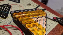
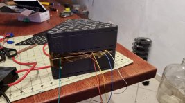
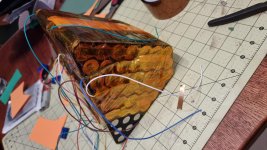
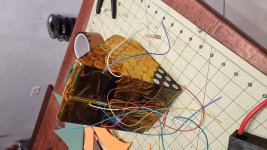
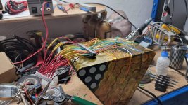
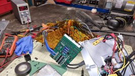
Then I was looking at your pics. Don't assume I'm right on this, it's just an observation. But I'm nervous about your balance wires. They're all running directly on top on the cells/copper sheets in a lot of spots, is that right? In some cases you have several of the balance leads sandwiched in between the two main sections. Bikes experience a lot of bumps and vibrations, and it looks like you built a dirt bike, so multiply that by 3. I'm concerned that the balance leads literally rubbed their insulation away and shorted against a neighboring cell group, causing discharge and damage. Have you already taken the battery apart completely to inspect for that kind of damage? It wouldn't take much exposed wire on the balance leads to cause this, it'd be miniscule in some cases. It would explain an overnight drain, and premature BMS shutdown. It would especially explain one cell group not registering at all; if the balance lead was cut or damaged enough, it wouldn't show up.

You could inspect all your balance leads (I know it'd be a pain, you put kapton on everything). Again, I'm not defending JKBMS because I think it's an infallible product, just want to rule out the obvious, fixable culprits. If you get your pack back to health and reassembled, you can reconnect the BMS and see if it works, before you scrap it and get a new one.
 
I mention this because it happened to me. Not with a big battery or JKbms, thankfully, but I had made a small 3s pack for a project, left it on my bench overnight, and found it in the morning dead, with a tiny blackened short on one of the balance wires.
 
Even if everything is undamaged and working as designed, many BMS are just as likely to murder the bank as protect it.

Preventing the cells from EVER dropping below your chosen LVC (SoC 0% definition) should be top priority.

Never trust, never assume, test and monitor with independent known-good instruments to see what is actually happening.

If you can, ensure the BMS can easily be removed and / or replaced as needed, get direct physical access to balance leads to observe voltages at the cell/group level, do not rely on pack voltage.

Cells should ideally be fully isolated from all circuitry to eliminate the risk of vampire drains, so only true self-discharge rates can be accurately ascertained.

 
john61ct said:
If you can, ensure the BMS can easily be removed and / or replaced as needed, get direct physical access to balance leads to observe voltages at the cell/group level, do not rely on pack voltage.

I did not do this for my first build. I'm absolutely doing it for my next. Nothing bad has happened to mine, yet, but I'd rather be able to independently monitor, and more easily swap out components myself, than assume something is just going to work
 
cjorgensenmd said:
A few months ago I built a 14s6p battery pack from Samsung INR21700-40T cells.

I recently took the top case off in order to install a new top with a VESC and 48v->12v converter. Everything was going great until I connected a voltage display. It should not have shown anything with the battery turned off, but instead it showed 26v.

I turned the battery on and connected the horrible JK BMS App. It showed most cells at or below 2v with one cell grouping not registering at all.

I am currently trying to resurrect my battery by removing the BMS and top balance charging each parallel group individually. My theory is the BMS did not actually turn off the output when I switched it off. It similarly failed to switch off the output when it got to the low voltage threshold. Has anyone else faced a similar issue with this BMS? It was fairly expensive and highly rated, so I did not expect to face this kind of an issue.

Also, any tips on resurrecting the battery? Right now I am just slowly charging each parallel group.

cjorgensenmd said:
So before changing the top on the battery, it had been sitting unused at about 54v. The smart BMS came with a small digital switch that is supposed to tell the battery to turn on or off. Either enabling or disabling the output.

My daughter had previously ridden on the battery several times without issue. I never disconnected the BMS, but I did need to unplug and re-plug the switch to fit in the new top case.

The bike was not ridden at all between replacing this top case. It was literally just left overnight, wired to the voltage converter and powered off VESC. I had presumed the battery also had its output disabled.

I cannot take a screenshot with the BMS disconnected currently, but my low voltage cutoff was set for a relatively modest 3v per cell.

I verified the readings were correct with my multimeter.


Thoughts based on the info provided so far, including notes that cover some possibilities not specified yet:


Most likely, if the DC-DC (48-12v converter) was left connected to the battery (overnight, etc), it drained the cells below empty (<2v).

If it was connected to the output (discharge, P-) connector of the BMS, then the BMS should have turned the output off and prevented that. If it was connected any other way, the BMS can't do this.

If the BMS didn't prevent that, but it was correctly connected, the BMS may be damaged (the FETs may have failed shorted, a common failure mode, leaving the BMS permanently "on").

If the switch to turn it on and off has a poor connection to the BMS itself, and is only a momentary switch, it may not be correctly switching the BMS--same for if the switch is momentary and isn't always making a good internal connection when pressed.

If it's a latching switch, and requires latching on to turn the BMS on, and has an obvious height difference when on vs off, should be easy to verify which way it's set at any moment. If it has the same height in either mode after releasing the switch, I recommend a different switch that you can visually tell if it is on or off to ensure this problem can't recur.

If the BMS has separate charge and discharge ports, but these were tied together, that bypasses the FETs both ways and defeats the ability to turn off the output or input.

Cells drained down below their spec sheet's minimum limit, such as yours at <2v, may be damaged and could fail at any time under any conditions.

Failures can include fire.

Even if they don't fail, they are unlikely to perform the way they were designed to; more voltage sag even under less load, lower capacity, greater heating during charge and discharge, etc.

It is safer to replace *all* of the cells in the pack with brand new cells than to attempt to recover these.

I recommend first testing the BMS to ensure it operates correctly first. With it disconnected completely from all the cells, you can safely use a multimeter set to Ohms or Diode test to measure from C- to B- and P- to B- and P- to C-, in both directions for each one (red and black meter leads first one way, then the other). Since it is not connected to the battery there is no power to turn anything on, so the FETs should read open circuit in the direction of normal current flow. So red lead on B- and black on P- should be open. Red on C- and black on B- should be open. Black and red swapped on diode test shoudl read a "normal" diode (usually 400-ish to 700-ish, depending on how your meter works). P- to C- should read open both ways, for BMS with separate charge/discharge ports. (common port BMS will read short circuit both ways).
 
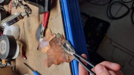
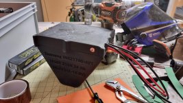
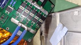
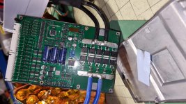
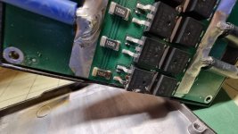
Ok so I tore the BMS apart and discovered one of the mosfets was blown and shorted out. So that would explain a lot except why did the mosfet blow? The only thing I can think of is possible mechanical compression when I was putting the new battery case top on. Anyone have other thoughts?

Is this worth trying to repair or should I just get a new BMS?

20221012_191715.jpg

20221012_191719.jpg

20221012_191735.jpg

20221012_192247.jpg
 
cjorgensenmd said:
Ok so I tore the BMS apart and discovered one of the mosfets was blown and shorted out. So that would explain a lot except why did the mosfet blow? The only thing I can think of is possible mechanical compression when I was putting the new battery case top on. Anyone have other thoughts?

Is this worth trying to repair or should I just get a new BMS?

20221012_191715.jpg

20221012_191719.jpg

20221012_191735.jpg

20221012_192247.jpg

I agree that until we can track down the "why", you may not want to rebuild the battery as is.

Similar thing happened to Youtube Off-Grid Garage with this BMS. https://www.youtube.com/watch?v=fZAbMFLzzIs
In his case he was intentionally pushing its charge and discharge capabilities. He makes an attempt to repair it. He also notes that after the mnosfet blew, the unit still "worked", presumably at a lower rating.

Interesting to note that you got the same symptom he had, and what he was doing was discharging a ton of amps. My money is still on there being a short, external to the BMS itself. Have you inspected all the balance wires underneath the kapton? I was also thinking about your symptoms, and that you had one cell group not reading voltage at all. The balance wire to that cell group, and its neighboring two groups, is where I would inspect first.

Amberwolf had a lot of great suggestions too, I'm wondering if you followed his recommendations for performing a resistance/continuity test with no battery connected. I'm certainly going to bookmark those instructions for myself, for when my JKBMS fails as well.
 
I've examined all the balance wires fairly thoroughly and have found no evidence of a short, but when I rebuild, I am going to be taking extra special care to isolate and shield all the balance wires per your suggestion. I haven't found anywhere else that would suggest a short and it's honestly difficult to believe that having the voltage converter hooked up overnight with no load would drain ~24 AH from my pack. The energy must have gone somewhere, but I can find no evidence of where.

With the BMS not hooked up to anything, it reads a short circuit across the the two leads. It is a common port BMS.
 
cjorgensenmd said:
I've examined all the balance wires fairly thoroughly and have found no evidence of a short, but when I rebuild, I am going to be taking extra special care to isolate and shield all the balance wires per your suggestion.
Again, please don't take this as a "you're wrong and you screwed up!" accusation, that's not it at all. It just seems like an internal battery short prior to the BMS is what happened. It would explain the missing cell voltage, that it happened after physical modifications that you were doing, that a mosfet blew, and that the cells continued to discharge after they reached your LVC of 3.0v and the BMS cut off. It did cut off when you checked it the first time, yes?

cjorgensenmd said:
The energy must have gone somewhere, but I can find no evidence of where.

Here's actually why I'm so invested. It's a good mystery and I would love to help figure it out! Huge amount of energy missing from the battery overnight, no sign of damage or shorts? Come Watson, the game is afoot!
 
cjorgensenmd said:
I haven't found anywhere else that would suggest a short and it's honestly difficult to believe that having the voltage converter hooked up overnight with no load would drain ~24 AH from my pack. The energy must have gone somewhere, but I can find no evidence of where.
There is always some current draw on a converter even with no load on it. How much depends on it's design. Some can be fairly high, in the 100mA+ range. I haven't seen one that would draw 2A or more unloaded (which would drain a 24Ah pack in 12 hours or less), but I suppose it's possible, if unlikely.

Controllers, if inactive (not driving the motor, but still powered on) can draw 100-200mA or more, so in say 12 hours they could draw 1200-2400mAh (1.2-2.4Ah) or more.

If the BMS has bluetooth, and it did not shutdown but kept powering that, it could also draw enough current to contribute--how much, I don't know, as I've never had one like that to measure standby current on.


Do you have a multimeter you can set to DC Amps? Or a wattmeter? If so, put it between the converter and a power source to run it (if you have a different one than this battery). (follow the meter's instructions for connecting it to read DC current--it is different from DC voltage or Ohms, etc). What current does it read, when no load is on the converter?
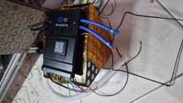
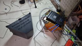
Similarly, how much does the inactive controller draw?

The BMS, if powered by just the main + and -, can be tested for current draw this way as well. If it requires the balance leads to be connected to working cells then it won't be testable without connecting it to a different pack of cells.

Any other devices connected to battery voltage can also have their standby drains measured.

Adding those together gives you the drain rate the pack would probably have seen, to be multiplied by however many hours it was in that state.


FWIW, a shorted pair of balance wires can only drain the group(s) they short across. For a single balance wire short to drain all the groups, it would have to be the most positive cell's balance wire, and it would have to short to battery negative (or any point electrically connected to that). Given the amount of current that would likely result, it would almost certainly "leave a mark", and could even heat teh wire enough to desolder it from the cell group it's on, or actually melt the wire (certainly the insulation), and probably cause enough smoke that you'd've noticed this immediately. If the resistance of the short was very high, it could drain the pack slowly enough to not cause other visible damage, but this is not that common with wiring faults.


With the BMS not hooked up to anything, it reads a short circuit across the the two leads. It is a common port BMS.

A short across which two leads? The P-/C- to the B-? Or something else?
 
cjorgensenmd said:
Ok so I tore the BMS apart and discovered one of the mosfets was blown and shorted out. So that would explain a lot except why did the mosfet blow? The only thing I can think of is possible mechanical compression when I was putting the new battery case top on.

It's unlikely a mechanical issue would cause a FET to fail, unless it caused something external to the BMS to short circuit across the BMS board itself causing excessive current flow thru the BMS (which would probably have continued until power was drained from the source, and probalby have done much more damage than that). If it shorted wiring, it would ahve also damaged the wiring itself, visibly, most likely, during the event--you would probably have noticed at the time and would see results of it's aftermath, too.


It's more likely that some momentary voltage or current exceeding the FETs ability to handle caused the failure.

Since the FETs that failed are on the discharge path, then the most likely thing to cause the failure is connection to a controller with capacitance high enough to cause momentary current higher than the FETs could handle while the caps charged up. It may even have survived this multiple times but finally failed at some point. The FET rating (see below) is high enough this is probably not the cause...but it could be. Some BMS failures we've seen have been suspected to be from this, especially when they happen more than once on the same system for "no reason", and in at least one case (can't find the thread ATM) they stopped happening after adding a precharge setup to it. (but it was a really big controller with presumably quite large capacitance).

But we probably can't know what the actual cause was, for certain, unless it can be made to happen again while monitoring and testing for those conditions; typically something you wouldn't do outside of a failure analysis session intended to improve a design. ;)


It's possible only that single FET failed, but it is also possible that any other FETs in parallel with it on the same path failed or are damaged (so that they will eventually fail) by whatever event(s) blew that one. It's also possible that simply removing that FET will let the BMS work normally, never to have a problem again (albeit at 9/10 of it's original rated current output capacity).


FWIW, this is probably the specs for that FET
http://www.szhxmos.com/uploads/soft/2101/HYG042N10NS1P.pdf
If so, it's absolute max voltage is 100v, and max current 120A. FETs in parallel share current but not perfectly, so in general 10 of those in parallel will be able to handle about 1200A absolute max continuous. But the pulsed drain current is a few times that, meaning just to charge up the caps, it should *probably* handle that fine, as long as the temperature is low enough (if the FETs are at room temperature).

RDS(ON)=3.5mΩ which is pretty low, and would be 1/10 of that for the whole path given 10 in parallel.

There is a single FET of the same p/n by itself that is probably the charging path FET.
 

Attachments

  • HYG042N10NS1P[1].pdf
    762.1 KB · Views: 6
My BMS has bluetooth and a common port, so the short was between B- and C-.

I will have to wait until I get home tonight to try those current tests you mentioned.

It's interesting that you mentioned charging capacitance current. I used to have a Kelly controller that bit the dust. (bad hall sensor inputs) I had it hooked up to this battery with XT-90S anti-spark connectors. One day though, the anti-spark feature stopped working and I would get a spark each time I plugged or unplugged it. I assume the resistor inside blew out somehow.

Perhaps repeated plugging and unplugging without that protection caused an over-current and blew the mosfet. My new controller has a new functioning anti-spark connector.

So if I blew the mosfet from hooking it up like this in the past, that might explain why the BMS could not shut off it's output. It may have slowly drained away and maybe my weakest cells were the first to hit 0v.

I did an experiment last night where I klipped off the legs of the blown mosfet, but continued to get a short across C- and B-. Is this expected behavior without the BMS receiving any positive voltage? No leads are hooked up to it currently.

I have gone ahead and ordered a JBD smart BMS, but I want to understand this issue fully before putting the battery back together.
 
cjorgensenmd said:
I had it hooked up to this battery with XT-90S anti-spark connectors. One day though, the anti-spark feature stopped working and I would get a spark each time I plugged or unplugged it. I assume the resistor inside blew out somehow.

Perhaps repeated plugging and unplugging without that protection caused an over-current and blew the mosfet.

Maybe, but I can definitely second that those anti spark connectors suck. I've killed multiple, they've never worked for me as advertised. But I also don't like that spark, it'll wear out the connectors eventually. I decided to make a switched connecter: xt90 male to xt90 female, with a heavy duty toggle switch on the positive line. Switch off, connect battery to charger, switch on. Now the spark occurs in the switch, which, if it eventually wears out or can't handle it, can easily and cheaply be replaced.
 
I'm looking into anti-spark switches now because the spark is not as big of a problem, but the inrush current might be. Both for the BMS and the controller. It looks like Maytech makes a few, though maybe a DIY option would be better.
 
cjorgensenmd said:
I'm looking into anti-spark switches now because the spark is not as big of a problem, but the inrush current might be. Both for the BMS and the controller. It looks like Maytech makes a few, though maybe a DIY option would be better.

https://boundmotor.com/product/power-switch/?gclid=CjwKCAjw7p6aBhBiEiwA83fGupZMIDOp0sX7e2g9PaK-SRtxWAAHf123-6K3rw3t9C2AyOBOHRJ6dhoC9uEQAvD_BwE

Like this? Haven't seen it before.

Of course my DIY suggestion isn't exactly anti spark, just moves the spark somewhere else I would rather have it. Not sure if I want to spend 50 bucks for that link. But I'd be interested to know if you get one and like it.
 
cjorgensenmd said:
My BMS has bluetooth and a common port, so the short was between B- and C-.
<snip>
I did an experiment last night where I klipped off the legs of the blown mosfet, but continued to get a short across C- and B-. Is this expected behavior without the BMS receiving any positive voltage? No leads are hooked up to it currently.

If it's a short both directions (not just reading a diode drop in diode mode, but an actual close-to-zero-ohms short), then it's likely that more than one FET has failed shorted--the one that actually exploded just happens to be the one that so far took the most current thru it and plasmafied it's insides. (they dont' share current perfectly even when working, and once they fail shorted their internal resistance can be significatnly different--the lowest resistance one will take the most current, and then they can actually explode if there's enough of that long enough to heat it enough).


It's interesting that you mentioned charging capacitance current. I used to have a Kelly controller that bit the dust. (bad hall sensor inputs) I had it hooked up to this battery with XT-90S anti-spark connectors. One day though, the anti-spark feature stopped working and I would get a spark each time I plugged or unplugged it. I assume the resistor inside blew out somehow.

As noted by others, the antispark connectors aren't always usable (can fail), depending on the situation.

The likely problem is too little power dissipation capability so the resistor eventually burns open after overheating enough times. This comes from too physically small a resistor; can't build much of a resistor inside those connectors. For some systems the resistor for precharge may actually be several times the size of the whole XT90 connector. It depends on the amount of capacitance in the controller, and the voltage of the system, and the time you would like it to take to precharge, which determines the actual resistance you'd use (ohms), and then the initial current x the initial voltage gives you watts, which you can use to determine the resistor size. If hte resistor is enclosed in something that doesn't dissipate the heat quickly enough, you'll need a resistor sized at least enough to handle the initial power. If it's got good airflow or is bolted to something that will draw the heat away from it, you can get away with a lower power resistor by some amount (perhaps as little as half the initial power).
 
Back
Top