Kona Stinky, no pedals, big block on swingarm.

Ok, I have found ( or manufactured) another hour of usually non-existant spare time, so the real build has begun. Real life is demanding, and does not leave me many minutes per week of project time, so this build may not be the quickest on record!
This is one of the reasons I have decided that things will be done in the quickest reasonable way rather than the best way, if the best way would take significantly longer. The other reason is that so often when a project is finished, you realise that there was a better way of doing part of it, or that it would have been better if one thing was longer / shorter / different to how you did it the first time. If you have invested a lot of time and effort making something beautifully, you don't tend to change it, but if you have put something together "quick & easy", it is easier to convince yourself to put in the effort to improve it.
If it turns out great anyway, then you have more time to put into other things, and you are riding it sooner..

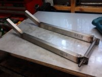
1) Cut and machined the ends of the four pieces of 304 stainless steel box section that make up the main rails of the new swingarm, 40 x 20 x 1.5mm wall thickness. Machining the ends in the mill may seem like overkill, but is in fact quick and easy, and there is no doubt that the ends are square and straight.

Why stainless? Most people avoid stainless because they believe that it is expensive, and that it is hard to work with.
Well, it is not as cheap as mild steel, but if you add the cost of the steel and the paint together on a project this size, it comes to more than the cost of the stainless, and the stainless item is made quicker because there is no "painting time". Yes, it is a bit harder to work with if you only have "home handyman" tools, but with good equipment available there is not much difference.
The "best practice" swingarm would be triangulated and made of chrome-moly steel DOM tube. It would cost more and take ten times as long to make, and modifying it later would be much more difficult.

2014-04-04 17.42.19.jpg

2) Clamped the pieces to the side of a larger piece of SS box section as a welding jig. You can see that the entire weld area is accessible while still clamped to the bigger box, and it is easy and quick to reposition the box in the vise so all welds can be done in the easiest position.
2014-04-04 18.25.31.jpg

3) There was nobody around to take a photo while I was applying the electric hot-melt, but it was done with a DC TIG welder on about 55 amps and pure Argon shielding gas. With a sharp tungsten, 55 amps gets good penetration and requires you to move quickly to avoid blowing a hole, but gives a smooth surface finish and (in my experience anyway) less distortion than welding on lower current and taking longer.
2014-04-04 18.22.55.jpg

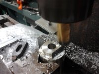
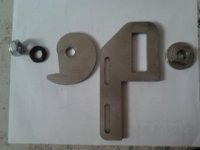
4) Back axle brackets were started. Two pieces of 40 x 40 x 3 stainless angle were cut at 41mm long. One leg was cut off at 21mm width and the long faces tack welded together. They were squared off and sized to 40 x 20 in the mill, and the 12mm hole (for the 12mm through axle of the back wheel) was drilled. In this way I know that even if the hole position is not perfect, at least both sides will be perfectly aligned to each other. Angle braces top and bottom are still to be welded on before these are welded to the box section.
2014-04-05 09.25.13.jpg

I will update again when I have found a bit more time to make more progress...
 
2014-04-11 15.49.27.jpg
I found another half hour, so managed a bit more progress.
Welded angle braces to top and bottom of the back axle brackets, squared off the back of the brackets, then cut the tack welds to separate them.
2014-04-11 16.09.09.jpg

The reason I tacked them together while making them was to get them as identical as possible, especially the hole position. As well as that, the minor stresses caused by welding in the angle braces are "equal and opposite", so the brackets support each other and minimise distortion compared to welding them separately.

I then tack welded the brackets to the back of the swingarm legs, and made a 142.5mm long tube to keep them spaced correctly during assembly.
The brackets are that distance apart to allow a 142mm wide back hub in future, but as the hub on the wheel I already have is 135mm wide, I will tack weld 3mm thick rectangular brackets across inside the main brackets to suit the narrower hub. These will be removed if I ever want to run a 142mm hub.
2014-04-11 16.12.23.jpg

I have only tacked them on, as I left the swingarm tubes a bit longer than my calcs show, as it is easy to shorten and re-square them once the trial assembly and the front pivot is finished. At this stage they weigh 1700g including the spacer tube and bolt, against the original Kona swingarm's 800g.
 

Attachments

  • 2014-04-11 16.17.17.jpg
    2014-04-11 16.17.17.jpg
    50.1 KB · Views: 4,188
Ok, time to make some decisions and spend some money..

Motor: Definitely the low kV "Big Block Alternative" nominal 48V 1000W brushless as sold by BHT;

Definitely a V3 Cycle Analyst to gather information and possibly assist in throttle control;

Controller: Kelly KBS;

Batteries: Here is where I would appreciate a bit of advice / confirmation (or otherwise) of my thinking..
15S 2P 5000mAh 20C LiPo. Each string should be able to provide 100 amps (5A x 20C = 100A, is that right?). So 2 parallel strings should be more than enough to get me the performance I want, and I would have around 600 Wh available.
20C packs are cheaper than higher C rate packs, but as long as I have enough capacity I don't need a higher C rate than neccessary.. there would not be any advantage.. is that right?
Dave
 
Swingarm Pivot bearings:
As mentioned previously, I am using the bottom bracket of the frame as the swingarm pivot. I will use standard external bottom bracket bearing housings, but the 6805 bearings used are not as robust as standard 6202 bearings, and cost more.
I decided to use 6202s, but their outside diameter is 35mm, 2mm smaller than the 6805, so I machined 2 adapter bushes to fit the 6205s into the external bottom bracket bearing housings.
2014-04-13 19.53.03.jpg


The 6202 bearings are 5mm wider than the 6805s, and I have left a 1mm thick flange at the back of each bush to locate it, so the width of the bottom bracket with the 6202s will be 12mm wider than original, so around 110mm.


I will make a compression tube to place between the bearing inner races so the pivot bolt can be tightened hard without crushing the bearings.
 
More progress: I have made the front brackets for the swingarm and tacked them on in the same way as the rear brackets.
2014-04-16 18.38.52.jpg

Swingarm trial fitted to the frame. I have left it longer than needed at this stage..
I have been given a 26" x 3" tyre and tube, and am having problems finding a 24" x 3" locally at a reasonable price, so it is possible I might end up using a 26" wheel, which would mean another 25mm swingarm length. This photo is with the 24" back wheel with skinny tyre.
2014-04-16 18.43.39.jpg

Hopefully tomorrow I will have a pair of external bottom bracket bearing housings with worn out bearings to fit my adapters and 6202 bearings into, courtesy of the local bike shop.
No more progress for ten days.. going away on holiday.
 
We had a great holiday, but we are home again and it is time to make more progress: my friendly local bike shop donated two external bottom bracket housings with worn bearings, and I have removed the original bearings and pressed in my adapter sleeves and 6202 bearings.
2014-05-01 20.08.54.jpg
As you can see, the bearings are a lot wider than the originals.

These bottom bracket sets are sold to fit both 68mm and 72mm bottom bracket widths on the frame. If you use them on a 68mm frame, you normally use the supplied spacer rings so the inside of the bearing housings are 72mm apart. I want the bearing housings screwed right in for strength reasons, and came across a minor problem:
There is a plastic tube supplied with these kits to keep any water and dirt inside the frame out of the bearings. It sits between the bearing housings inside the bottom bracket, and has O-rings to seal it to the bore of the bearing housing at each side. It also has a ridge or flange at each end to prevent it sliding too far into the bearing housing, and these ridges prevented the housings coming close enough together. I simply ground the ridge off at one end of the tube, and it could then slide in the extra 4mm into the bearing housing to allow the housings to be tightened right in against the frame.
2014-05-02 19.49.08.jpg

I bought a stainless steel 16mm bolt and machined it down to be a nice fit in the bores of the bearings, as a pivot bolt for the swingarm. The central area of the bolt which will be between the bearings was machined down another 0.1mm so it will slide easily through the bearings during assembly / disassembly.


Next step is to assemble the bearing housings in the frame and accurately measure the width between the inner races of the bearings, and make a matching compression tube of 3/4" (19.05mm) outside diameter x 1.5mm wall thickness stainless tube, to support the inner races when the pivot bolt is tightened.
 
More progress: The pivot bolt is finished and two 10mm wide spacer bushes are welded to the inside of the front swingarm brackets to set the width of the swingarm.
2014-05-11 16.41.05.jpg

The outside width of the swingarm bearings in their modified housings ended up at 98.3mm, narrower than I had expected by a few mm, but I had planned to have spacer bushes anyway, so made them a bit wider to get the inside width of the swingarm 142mm. With the front pivot bolt and the back axle tightened, the swingarm feels reasonably stiff, and there is still a lot of bracing to come, plus full welding and attaching the rear suspension link, so it will stiffen up a lot more.

I am buying a hub with a 6-bolt disc flange at each end, so I can mount a sprocket on the right side and a brake rotor on the left. This hub is a bit narrower than a standard mountain bike rear hub (128mm rather than 135 or 142mm), so spacers of some sort will be needed at the back of the swingarm.
I had intended to have the back axle solidly mounted and adjust the chain tension by moving the motor, so the rear disc mount would be easy, but now the swingarm is taking shape I have found that the motor will sit very nicely if I weld a plate across the bottom of the swingarm at the front and bolt the motor to it. The downward angle of the front of the swingarm has reduced the length issue caused by the mounting feet, and the motor sits well forward without hitting the seat tube when the suspension is compressed.
2014-05-11 16.56.06.jpg
2014-05-11 16.59.10.jpg
I now plan to use slots for the back axle and a slotted bracket for mounting the rear disc caliper, like bzhwindtalker in his current build
http://endless-sphere.com/forums/viewtopic.php?f=28&t=57668 .
I think the axle position will need to be locked well, as will the caliper position, but I am sure that can be achieved, so I will carry on and finish the front of the swingarm.

I will buy a wide 24" rim and 3" tyre for the back wheel.. an expensive wheel but it should work well.

Slow progress, but it should be finished for our southern hemisphere summer!
 
Some more progress.. I have drawn up a few components for waterjet cutting, made a couple more, and received my double - disc - flange rear hubs from ES member Stevil-Knevil.
I have also bought a wide, strong 24" rim and 24 x 3" Duro Wildlife Leopard tyre and inner tube. (So much for the "build it cheap and upgrade what breaks" idea.. now being done right the first time). No photos of the rim etc yet.. the rim and hub are at the LBS getting spokes organised.
I decided to be adventurous, and tried to contact YK Success Ltd in China, who as far as I can see actually manufacture the "Big Block GNG Alternative" motor I want to use. They advertise this motor at 500 Yuan, which is about half the 99 Euro being asked by BHT. However, I have waited 10 days and no reply to my e-mail, so BHT will get my money.
 

Attachments

  • 2014-05-30 17.00.47.jpg
    2014-05-30 17.00.47.jpg
    57.7 KB · Views: 3,835
  • 2014-06-07 12.08.56.jpg
    2014-06-07 12.08.56.jpg
    30.8 KB · Views: 3,835
I got the rear sprocket adapter back from waterjet cutting today. (Anyone in NZ who wants waterjet cutting done, I have put a lot of work through Roadrunner Manufacturing in Bulls, and have always been very pleased with the result, the service and the price).
Couldn't resist getting out into the cold workshop and finishing it this evening.
2014-06-11 20.08.45.jpg
2014-06-11 20.42.37.jpg
2014-06-11 21.25.06.jpg
2014-06-11 21.23.12.jpg

For information:
The kart sprockets have a bore of 116.1mm (I think that is nominally 4 9/16") and are attached with six M6 bolts on 5 1/4" (133.35) PCD.
The disc brake mounting has a spigot 32.7mm diameter (on my hub anyway..) for a 33mm bore in the disc (or sprocket adapter) and has six M5 bolts on a 44mm PCD.

I will take the adapter to work tomorrow and weigh it, and post the weight here.
Edit: It weighs 145 grams as I machined it. If I were to do another I think I could get it down to 120 grams easily, possibly lighter if I tried hard..

Good to see more progress!
 
There are sevral suppliers for a left-side spider to attach a bicycle chainring to a rear wheel hub, but...this is the first #219 Kart chainring adapter I have seen. Have you considered making up a few for sale? Beautiful work, mate!
 
Hi Spinning,
I expect that someone has made something like this before, but I guess the higher power mid-drive type motor becoming more readily available will make them more common.
This will be on the right of my double-disc-flange hub, with a standard left side disc brake, but of course it could be mounted either side to suit different applications.

Making a batch of them would be no problem if there was a demand. I would guess around $60 each plus shipping from New Zealand to wherever, but at only 145 grams the airmail wouldn't be too expensive.
If I got say 2 people interested I could do a batch of 5.

I got 2 cut, so if one person wanted one I could supply quickly.

My spokes are on their way, and I am getting the LBS to build my back wheel as it really needs to be done well and I don't have any specialist gear. Hopefully I will have the wheel next week.

Meantime, a couple more purchases arrived:
2014-06-12 19.41.25.jpg
2014-06-12 19.43.43.jpg
 
Two new toys arrived today, one small and one big:

1) The controller turned up from Kelly Controllers: a KBS72121X. I find it hard to believe that such a small unit can punch out the power it claims (rated at 72V, 120A peak, but other users are pushing them beyond those figures), but it does feel reassuringly heavy for its size...
I paid extra for waterproofing.. I tend to ride through streams and mud and I don't want the smoke leaking out because of a bit of moisture..
2014-06-24 20.58.46.jpg

2) The Local Bike Shop finished lacing and trueing the back wheel, and I have fitted the tyre:
Double disc flange hub from Stevil-Knivel, 50mm wide double wall rim and 24 x 3" Duro Wildlife Leopard tyre. Looks staunch:
2014-06-24 20.57.20.jpg

Still awaiting the motor.
 
Here's how the back wheel looks in its furthest back position.. the adjusters will let it come up to 25mm forward of this position.
The gap between the back tyre and the motor will vary between 25 and 50mm. I want to put some sort of mudguard here to protect the motor from mud, rocks etc thrown by the back wheel, so I think this will be ok.
View attachment 1
And here's a first try for footpeg position:
2014-06-25 20.54.23.jpg
 
Hi Drum,

I realy like your build!
As you wrote, the only issue with a swing arm mounted motor is the wider wheelbase. Appart from that I realy like the idea of swing arm mounted motor. Especially the BHT Motor will fit very good for this system.

Why didn't you use midsteel, appart from the paintjob thing? Did you heat treat the swingarm? I think with the right crabon midsteel stiffness would be the same as stainless steel. You could also save weight by using thinner profiles with stiffer midsteel.


I paid extra for waterproofing.. I tend to ride through streams and mud and I don't want the smoke leaking out because of a bit of moisture..

2014-06-24 20.58.46.jpg

I also bought the waterproof version. It is compleately sealed with silicon. Took a ride last week when it was very wet and a lot of mud was on the controller. after cleaning the bike the controller was compleately dry inside.


.. Jacob
 
Hi Ferret and Jacketful,
Thanks for your comments!

Footpeg position: Yes, footpegs mounted to the frame, or at least a non-moving part of the swingarm close to the pivot, would be better. If I was building a frame from scratch, I would build a twin cradle frame like BZH has, and have a good place to mount the pegs. However, I am using a standard bike frame, and there is nothing to mount footpegs on other than the swingarm.
I thought about making a subframe to hold the footpegs, but it would not be easy (or lightweight).
Personally, I have always preferred footpegs on off-road motorbikes positioned further back.. it makes standing on the pegs more comfortable, and in the terrain I ride in most, you spend a lot of time standing.
Everything is a compromise.. the further I move them back, the more comfortable and capable I expect to be when riding, but there will be shock coming up my legs from bumps, and the unsprung weight will increase, which will make the back suspension less effective.

So, I am going to pick a position and try it. If the shocks coming up my legs are too great, or I feel that the back suspension is working too hard, I will move them further forward.

Stainless: The stiffness and strength of mild steel and stainless steel are similar. If I could have got chrome-moly tubing I would probably have used it (and bronze-welded it), but in New Zealand it is rare.
I work with stainless a lot in my job, and I enjoy the low maintenance and lack of corrosion from its use. I will have to keep an eye out for fatigue cracking along the welds, but at least they will not be masked by paint!
I expect the bottom of the swingarm to be sliding over logs, dirt and rocks when I play Trials, so paint would be scraped off, which is the main reason I chose stainless.
 
Yeah, if you're building from scratch or for prototype build midsteel is the best way to go. It's easy to work with and expensive. I build my first frame compleately out of midsteel. One of the reasons was that I only had a MAG welding machine.

I used tubes wit about 2mm wall thickness. The material I used was not very stiff so i had to use thicker tubes which makes the whole bike realy heavy.
CrMo would be the best but also not easy to work with. Looks liek you have experience in welding stainless steel. Is it hard to weld without heat treat the material and get no tension- cracks in the welds?
I would love to work with stainless on my new build but is's a hard decision.
Should I use stainless or rather aluminium like 6060 or 7075??

...curious to see your bike running with the BHT ;)

This motor already seems to work great as Swing arm- drive:
http://endless-sphere.com/forums/viewtopic.php?f=28&t=59122
 
Hi Jacketful,
Just looked at your build thread.. looks great!
If this bike works well, but the footpeg position etc seem to limit it, then the next step would be to build a frame and transfer the electrics across to it.. then I could avoid having to make so many compromises.
Before that though, I will be building an electric trials / trail bike similar to the Oset 20 but a bit bigger, for my 12 Yr old daughter to ride (and her father to have fun on..). Again, I plan to bolt the motor to the front of the swingarm, but with a twin cradle frame so the motor can be virtually at the pivot point of the swingarm, and the footpegs can be well back but still be on the frame.
Got to finish this build first..
 
My motor has arrived!
BHT brushless motor with hall effect sensors, nominal 1kW @ 48V, but proven to be capable of much higher performance.
A few fins slightly bent but no significant damage.. the box was still in good condition.

It took about 15 days to arrive to my small town in New Zealand from date of order. The parcel was dispatched from Malaysia by DHL express.

I put it beside my wooden model, and was pleased to see that it was slightly smaller than the model, so should fit ok where I planned.
Unfortunately I do not have enough spare time to get out to the workshop and mount it immediately, but hopefully I will make some more progress soon.
2014-07-04 21.30.10.jpg
 
A bit more progress: I got the swingarm halves cut down and the rear axle mount brackets welded on.
2014-07-10 15.21.15.jpg
2014-07-14 08.19.58.jpg


I have also had my motor and controller connected and working on 24V, and had a bit of a play with the controller settings. I still have a lot to learn about setting up the Kelly controller to get the best out of the motor.
 
Looks good!

Again, I plan to bolt the motor to the front of the swingarm, but with a twin cradle frame so the motor can be virtually at the pivot point of the swingarm

Haha thats exactly what I've planed in my new buid!

If the Motor is mount in front of the swingarm, the only problem I see is the distance it would draw closer to the ground when rear wheel is fully suspended.
bike.jpg
front_mount.PNG
I plan to make a new frame, where the motor sits directly below the pivot point of the swingarm!


Looking forward to your progress!

.. Jakob
 
Hi Jakob,

Having the motor mounted to a swingarm forward extension like your drawing shows can work for bikes used on the road, but I would not mount a motor that way for an off-road bike.
As you say, ground clearance would be an issue when the suspension was compressed, but also the "unsprung weight" effect caused by the distance between the motor and the pivot point would be noticeable.
WHen I said I would mount it on the front of the swingarm, with a twin cradle frame, I meant mounting it really close to the swingarm pivot, which would be possible because it could be between the frame tubes. On my current build I cannot put the motor any further forward because it would hit the seat tube of the frame.
Dave
 
Hi Dave,

"not for offroad use" .. that's for sure!

but also the "unsprung weight" effect caused by the distance between the motor and the pivot point would be noticeable.
Just wanrt to test the BHT on the Swingarm first. Plans for my new build will be to have the motor plus batteries as low as possible. So motor will be mounted below the swingarm pivot.
All made out of aluminium (plasma; plasma cut :) )
BHT_Swingarm.PNG
 
spinningmagnets said:
There are sevral suppliers for a left-side spider to attach a bicycle chainring to a rear wheel hub, but...this is the first #219 Kart chainring adapter I have seen. Have you considered making up a few for sale? Beautiful work, mate!

Second that!
 
Back
Top