Li-Ion Battery Pack Building Techniques

jbnimble142

1 µW
Joined
May 18, 2023
Messages
3
Location
somewhere....
Hello all.. I am in the process of building my 3rd battery pack, the 1st was a 72V spilt into 2 packs of SPIM08 modules thanks to youtube vids by jag35.com. The build method of using a hole punch and brass connector which was pressed worked well, that is until I shorted a pack by stacking to sets of batteries together and then trying to connect them. There are no shortcuts. I recently had a great discussion with the sanitation battery drop-off guy as 1 of the modules was still in good condition.

I had used an active battery balancer and it was not capable of performing the required amps needed by the motor, thus the Voltage dropped significantly and the 1 pack @36V was lost under load. From then I have moved to 18650 cells, the last pack I used Samsung 22P cells rated 10A/cell, I found a very useable spot welder and created a 17S5P pack in a 91-cell downtube case, it works very well.

My question is regarding the "P" in the configuration where the poles, both positive and negative have the same number of cells as the "P" configuration. Since the 91-cell cases are primarily for 36, 48 and 52-V builds when building larger series configurations you have open spaces in the battery holders. My thinking is that I can use these spaces to make the poles larger, for instance in a 17S build I could make the positive and negatives poles 6 or 7 in parallel and the rest of the cells in a 5P configuration. Could anyone comment on whether the draw from the poles would be too much for the pack. (I am using a JBD smart BMS and under load I noticed the B0 cell was drawing "red" and got bumped off the reading under high amp draws, I figured a larger pole would rectify this issue).

In all after 40 some odd cycles in the 5P configuration the cells are holding steady at .004MV balance... Should I on the next build play with the number of cells in the poles to offset the visual bumping I see in the BMS app.... Thanks!!!
 
My setup:

BaFang BBSHD w/ ERT ASI BAC 855
JBD smart BMS @60A-17S

The video was used to determine the amp draw on the e-bike system, the blinking red modules I assume had reached a warning level, although the video only shows what can be seen by the phone, it only shows the first 6 modules in a 17S configuration. I assume the red warning light is moving throughout the 17 modules.

(passcode: SamSung6788)
 
My question is regarding the "P" in the configuration where the poles, both positive and negative have the same number of cells as the "P" configuration.
I don't know what you mean by that. You'll need to be specific using numbers and Parallel / Series configuration, pattern of interconnects, etc. Usually best conveyed by pictures of the pack interconnects from both sides, and a description of exactly what you mean by "poles".


A pack made of the same cells (assuming they're new and not say, recycled garbage that have random capacities and resistances) must have identical numbers) should have identical numbers of cells in each parallel (P) group.

The P groups should also each have enough cells to be more than capable of handling the peak and continuous current the system requires, so that they are not loaded to the point they have significant voltage drop or heating. (if they get hot, there are not enough cells; even warm is not ideal).


If you have less cells in any group, that group cannot handle the same amount of current as the others, or have the same capacity as the others.

Assuming all the groups are easily capable of handling the currents required, and have more than enough capacity for your range needs, then If you have extra cells in any group, those cells don't "do anything" except add weight, complexity, and extra potential failure points.

If you had more cells (equal number) in *every* group, then those are not "extra" because the entire pack now has less load on it, and spare capacity for detours, headwinds, compensating for pack aging, etc.


Could anyone comment on whether the draw from the poles would be too much for the pack.

You would have to specify the actual current the system draws peak, and continuous, (and any worst case data or intent you might have) and specify what your actual cells in use are (so we can find their spec sheets and any testing site data), and their source (since many sources do not have new matched cells, or sell seconds, low grade, or random unmatched cells, etc). You note Samsung 22P, but not the source, etc., whcih is important to know what they are capable of.

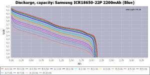
This page
shows what one version of the cells is actually capable of; at 10A they have extreme voltage sag (even at only 2-3A it's not very good), so really a 5p pack isn't "capable" of even 50A, as it will sag in voltage so much that you will lose a lot of power as heat in the pack itself instead of feeding it to your wheel. It also won't give you more than around 1.5Ah per cell of capacity, as under a 10A load a good safe LVC setting in the controller (3.1-3.3v/cell) would shutdown the motor at that point.


1698691951405.png


You'll also need to tell us exactly what you mean by "poles".


(I am using a JBD smart BMS and under load I noticed the B0 cell was drawing "red" and got bumped off the reading under high amp draws, I figured a larger pole would rectify this issue).

What does "bumped off the reading" mean?

If you mean that the cell group stopped displaying a voltage or went to zero, it means either the cell sense line or the BMS is defective, or that the cell group being monitored has failed.

You would need to use a volt meter to check the actual cell group voltages. If they are not identical between each P group, the cells are not matched and you will always have balance problems, taking potentially a very long time to finish charge (balancing can take hours, days or longer depending on the differences in the cells) and problems under load at low states of charge.


In all after 40 some odd cycles in the 5P configuration the cells are holding steady at .004MV balance...

Do you mean that after completely draining the pack they are still only at that difference? Or is this only after a full charge and however long it takes for balancing?

The former means the cells are well-matched.

The latter only means that the BMS is doing it's job of balancing them, but tells you nothing about the cells properties or conditions. ;)
 
Last edited:
If you build a 13-5P, but make the two end groups 7P, those two groups will discharge less than than the other 11. Run it down til the controller shuts off, most of the cells will be at 3.3V except the two on the end will be at 3.5V (this is an estimate), If your BMS can balance well, everything gets back to 4.2V at full charge, but it will take longer to get there. If your BMS cannot balance, the other 11 cells will be stuck partially charged at 4.0V while the two ends are at 4.2V. You've reduced the capacity of the battery, and with time, the voltage gap between cell group rises. Eventually, you have to rebalance manually,

The 22P is a good ebike cell, in my experience. Had them in hiverboard packs and they lasted 5 years before they got tired. I took them apart and rrebuilt as two 10S-5P packs. Effective 1.8AH still, compared to original 2,2AH, but high voltage sag, Still trust them for a 30 mile ride..
 
Thanks to both for the reply, @docw009... I had the same notion that the charging and discharging might be uneven and you probably are correct in the reduction of the voltage capacity of the pack. Your logic is making sense.. Interesting....

@amberwolf... thanks for the info but I am a noob at this stuff. My next pack will be made from Sony VTC5a cells probably in a 20S4P configuration or a 17S5P configuration , I expect to have more power and a longer lasting pack in that the VTC5a is probably good for 28 - 32 Amps/cell.
 
My next pack will be made from Sony VTC5a cells probably in a 20S4P configuration or a 17S5P configuration , I expect to have more power and a longer lasting pack in that the VTC5a is probably good for 28 - 32 Amps/cell.
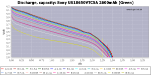
I'd say you'd be better off keeping it at half to two-thirds of that, based on the testing.

(in any of these charts, the lower down the line is on the screen for the current you want to draw, the worse the battery is being stressed by that current, the worse the voltage sag, the greater the heat, and the less power and capacity you can get out of the pack)

1698703079612.png
 
Back
Top