methods LVC/HVC/Parallel -> documentation thread

I try to always ask the question, because there are a fair number of people that know better but still do something they ought not to, without thinking about it. ;)
 
amberwolf said:
I try to always ask the question,

Sort of why I asked about the question about paralleling the packs (both main and balance leads) while the LVC/HVC/Protection boards are still in series via the data lines. It just seems wrong, wiring a board in series and parallel at the same time, though electrically they are not.

I had read some where that the battery side is galvanicaly isolated from the data line, but I wanted to double check. I finished my last canister of smoke to re fill the wires so did not want to take the risk of lettin gany escape from the boards or the packs, but any how I am not sure that late 80's Lucas smoke is compatible with modern LiPO.
I did see some new smoke, but I cant seem to find a supplier for it ( New Magic Blue Smoke ) in the UK.

Smokekit2.jpg
 
That smoke in a jar seems to be a great solution, I do have a burned 18 fet controller, can I restore the controller too ? How much PSI pressure should I use ?
 
Nah, It won't work pretty sure it isn not compatible..you would b better going with the Magic Blue Smoke


Description: On a recent trip to South America I made a shocking discovery. Deep in the Pacaya-Samiria National Reserve, our team came across a rare vegetative moss. The spores of this ancient plant proved to be quite useful to us. Through specialized process, we were able to carefully extract the dust from the spores and refine them into a very fine powder. Through a serendipitous accident in our research labs, a bit of this powder was let out into the air. The plume traveled across the lab and came into contact with some broken equipment we had piled in the corner. Like magic, the equipment came to life and was revived.

We toiled day and night to find the best way to harness this awesome power. Through a proprietary procedure using our inverse tetra-grammatron phase inductance focusing screen (TGPIFS for short), we were able to easily resurrect any IC reliably. Simply place the phase ring of the TGPIFS directly over your IC, inject your smoke, and you're done!

This kit comes with a single TGPIFS, an applicator pre-filled with spore powder and is capable of resurrecting approximately 20 ICs (depending on size, complexity, and damage).

Note: Please use in a well-ventilated areas as the fumes may be harmful.

Specifications:

12v, 150A input for TGPIFS
Applicator good for roughly 20 ICs
Kit designed for SMD or PTH
Disposable applicator
 
amberwolf said:
:lol:


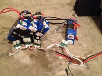
Actually the data lines are already parallel, rather than series.
??????

On a low level basis maybe, I have no idea how the boards are built..but if three boards are in a line connected by two cables..it looks to be in series
 
Series (in electrical terms) would be if the potentials between the lines are more positive on one set than another, but they are all at teh same potential (per wire) on the data lines, making them parallel.
 
It's not just "my thinking". ;) It's how it iis wired: The wires are directly connnected to each other, for all the LVCs on all the boards, and all hte HVCs on all the boards. That's pretty much the definition of parallel, right? ;)


Either way, since the HVC and LVC are electrically isolated from the batteries themselves, it doesn't really matter how (or if) they are connected--they won't affect the rest of the battery connections.
 
Think of the data line as a buss.
6 wires running in a big long line
Each LVC/HVC Parallel board taps into this data buss in parallel

So even though it appears that the boards are wired together in a chain (in series) in fact they are all wired together in parallel.

Here is how it works:

There are 6 wires.
3 wires for HVC
3 wires for LVC
LVC and HVC work the same - so lets talk only about LVC

5V
Sig
Gnd

5V is just that - 5V. Hooked up to 5V and it is basically the power for the output of the opto couplers. It need not even be connected - but rather it could be shorted to signal. It is only there to improve sensitivity for cold weather applications.

Gnd is just ground - just like ground in an automobile. It is required. Every boards output opto's use this ground. They are all referenced to it

Now Signal... Here is how it works. Think of signal as being a chain hung in a wall in a building.
Imagine if at every floor of the building there were a hole cut in the wall and you could grab the chain and pull it down
Pulling the chain down would sound a horn
If the guy on the first floor pulls the chain the horn blows
If the guy on the 5th floor pulls the chain down the horn blows
If they both pull at the same time the horn blows
If they both let go the horn stops blowing

The horn in this example is the opto outupt - which is active low
This means that when the horn blows the opto will short circuit the SIG line to the GND line
IF you happen to wire the SIG line across your throttle line (in parallel) then when the horn blows your throttle gets shorted out
That is how we stop further discharge
Consequently - this is also why we need to put a resistor inline with your throttle... so that when we short it out we dont draw too much current. We want to use a "current limiting resistor" and that is why it does not matter if it is 1K or 5K.

So one side of the boards is all detectors
They are stacked in series and could get upward of hundreds of volts

Each one of these detectors controls an OptoCoupler
This is a device that when current is applied to one side - a short circuit appears on the other
More specifically - if the detector runs current into the optoisolator a diode turns on inside
The light from this diode jumps a galvanically isolated gap - and hits a little photodetector
The little photodetector (solar panel if you will) is tied to the base of a transistor
The energy it produces (from the light of the diode) is used to forward bias the transistor which shorts out SIG to GND

Ok

There are actually two transistors out there - called a darlington pair
One is used to bias the other - this greatly increases gain
That is what the 5V is for.

IF you short 5V to sig then you loose the darlington pair advantage

Hope this helps guys.

Thanks Amberwolf for helping out.

-methods
 
I get the HVC (High Voltage Cut-off or High Voltage Control) principle, but isn't the n-chan mosfet just going to add a diode drop in the chargers path?

I've built a LVC for my GF's bike that is similar to this. It works for LVC, but I can't see it working as HVC.

Care to elaborate on this? :)
 
The discharge path is not through this device.
As you say - you can not block current in two directions with only one set of mosfets. To block in both directions two sets of mosfets hooked up drain to drain or source to source would have to be used.

In this case - the breaker is hooked between the charger and the batter in the ground path.
Charge goes into the battery positive, out the battery negative, then runs into the Drain of the four IRFB4110 fets. This is the blocking direction... i.e. the cathode of the power mosfet if you will.

Normally the circuit sits enabled - mosfets on - so that current passes
If an HVC event occurs then a latching relay cuts power to the mosfets and they turn off
In that case there is no longer current running

That clear things up?

I have two different models here on my desk
One has TO-247 mosfets strung in series to allow breaking of both charge and discharge current... but that design is a fail since you get double the waste heat while discharging and overkill mosfets for breaking charge.

The other design uses TO-247 mosfets for the path from the battery to the controller - then TO-220 fets for the path from the battery to the charger. Now the charge breaking section does not have to carry the full system current and the discharge section has half the waste heat.

Anyway - this is what "next years model" will look like.
Breaking of both charge and discharge current (to 0.0A OFF condition)
Then the throttle connection becomes optional - so this could be used for a 4S car battery replacement or a 30S ebike pack. For those running motorcycles it can be used to drive the main contactor.

-methods
 
I've got the HVC alu breaker and I can see in the documentation it is rated at 70A cont, and that it would then become about 65C. In light of these new information about the direction of current through the HVC breaker, I was wondering if the same temp rise applies in both charge and discharge. I was thinking of mounting the HVC breaker inline with discharge leads, so all current goes through it (both charge and discharge). But I do not want to do it, if it means having a small heat oven inside my battery case while driving. I never charge above 10A, so the temp would not be a problem during charging.

Any thoughts on this?
 
I a sorry - it will only run in one direction... so you have the choice of having it break discharge current or break charge current. You cant have both.

As far as heat - the probable reality is that your average current is really more like 20A or 30A so that thing would not even start to get warm in a bike application.

new subject:

I just got off the phone with liveforphysics and I think we are going to change gears for this season. I have been working on a bi-directional version of this years breaker that would completely isolated the battery for 100A discharge and 50A charge, as well as handle pre-charge... but I think we can do better than that.

Contactors have been getting smaller and smaller. Finally they are small enough for an ebike application. So right now I am working out a new system for this years battery protection:

* Small contactor capable of ebike level charge and discharge
* Handlebar mounted switch that turns the entire ebike system on and off (just leave the controller turned on if it has a switch)
* Contactor automatically pre-charges controller caps to 100% in very short period of time - no arch and no wear and tear
* Contactor blows open if any cell drops below 3.0V or rises above 4.25V regardless of power switch condition
* Circuit would draw a bit more power when ON - but would draw 0uA when triggered off. Circuit would draw microamps when switched off.

Yea...

So I am going to go draw it up right now. There are only a few cases to address.

* Switch off, LVC event, HVC event
* Switch on, LVC event, HVC event

I am seriously thinking about combining the LVC and HVC events - to just be an "event" - but this would hurt backwards compatibility. For motorcycle applications they want LVC to squelch the throttle and they want HVC to terminate the charge current. It is important that the LVC lines that hook to the throttle do not create any dangerous ground loops back to system ground.

Hmmmm....

Maybe we could eliminate the entire throttle squelching by having the relay cleverly wired such that it can both terminate charge current and remove the enable voltage from a controller.

Anyway - just thinking out loud. Going to go work this out. Coolest part is that we will now be good from like 12V to 1000V - no more voltage limitations. No more directional issues either... No more requirement to break ground - it can be high side or low side.

This is going to be FTW.

-methods
 
Sounds like a positive step forward.

I run a contactor on my 100v setup. It has a magnet that bends the arc on disconnect. No problem turning it off, even under power. The problem has always been turning it on when I forget to hit the pre-charge switch. It will weld the contacts EVERY damn time.
 
If I plugged my HVC boards in before, I paralleled my cells, and got a tiny arc, did I fry the boards?
 
Where was the spark?
If it was on the Andersons there is no problem
If it was on the communications line there is a Serious Problem
If it was on the balance tap lines then I will need you to return them (so that I can test them) and I will send you out replacements.

thanks,
-methods
 
FYI - order of operations is not really critical. Please provide more information if you want more insight into what may or may not have happened.

-methods
 
It was on the balance ports for the packs, I assume that the packs were trying to level to one another, even though they were only a couple of milivolts apart.
 
No - you are never going to see a spark in that situation. I would re-evaluate what happened because it is highly probably that something got mixed up. If the pins look burnt then I can guarantee that something was amiss.

Were the packs already hooked up at the power level? If they were then I would say that a pack from one group got mixed up with a pack from another.

Not worth the risk in my opinion - pack up the damaged board and send it back to me. I will make sure it works perfectly and get it back to you.

-methods
 
I agree not worth the risk. Because of this messy situation I have redesiged my pack to be less like spagati junction Lipo.

See post number 80.

http://www.diyelectriccar.com/forums/showthread.php?p=359246#post359246
 
Hi All,

Long time no post!!
i'm just about to wire Methy's boards and HVC breaker, i studied Richie's excellent diagram and then also Methys pics and i think i'm ready to have a stab at it.
I have come to the conclusion that i am in fact a little stupid, i've had my bike for about 5 years and i still don't know shit, so bare with me whilst i take my usual stance of asking stupid questions, getting confused and not trying to wire my bike and then coming back and asking the same thing.

I'm setting up exactly as in Richies diagram 8 x 5s turnigy's, i have Methy's boards and the newer potted HVC cutoff, to keep things very simple i wont go into the charging aspect until i get some pics up, so here we go with just setting up to ride, i'll charge the packs individually until i know what the hell im doing, again the diagram confuses me with this aspect.

1) i have a mini moto kill switch - how and where do i need to wire it?
2) i don't understand the HVC breaker setup, if the setup goes hvc does it cut the pack? also do i need an inline fuse on the pack well as the one in the diagram?
3) In Methy's pics the throttle setup seems to differ from the diagram, are they the same thing? can i put the throttle on any board?

I'll get some pics up tomorrow of my chargers, they do 10s charging/balancing and i think iirc they have 2 channels - would i connect these to the balance leads in order to cahrge? do i need to diconnect the main pack from series in order to do this correctly?

you know what forget that question, i'll lay everything out on the floor and take some lovely big pics so you guys can steer me right, but if you can tell me the basic answers on the kill and how the HVC works that would great.

I can't believe how long i've been away from the forum, missed you guys!! i've been very busy with Mini Deec, his goose CX is waiting for him :)
 

Attachments

  • away.JPG
    away.JPG
    23.9 KB · Views: 2,045
Ok, so my setup is below, it's exactly as per Ritchie's diagram for battery config and im happy that I can follow Methy pics to connect up, however for ease of understanding i'll reference Ritchies diagram, a few things I don't get:

1) Is the new potted HVC the same as the old unit in that if the fets are at the top (as shown) then the left cables go inline with the pack to the controller? do I just need the one fuse?

2) In Ritchie's diagram the right side cables from the HVC are indicated as going to charger? I don't understand this because I thought the "data" connectors were isolated from the battery connections?

3) Can I connect my throttle to any board? im planning to install the 1k resistor and cable exactly as methys pics - this gives the same connection as Ritchies diagram no?

4) In my limited understanding my best method to charge would be to disconnect the batteries from series and leaving the balance leads connected to methys boards connect my chargers to those boards and charge 2 packs through the balance leads by setting the charger to 10s and using chA for 2 batts and chB for 2 batts (see charger pics) - im figuring I will need to read the charger doc to find out what the pin outs and possibly make up my own leads? (I think Jozz made mine so I can plug the batts straight in, i'll check).

I've posted a few pics of my charger and i'm off hunting the tech doc.

Would you guys be so kind as to have a look and warn me in the most simplistic terms if im doing anything I should be!!!


Cheers,

Deec
 

Attachments

  • setupSMALL.jpg
    setupSMALL.jpg
    147.7 KB · Views: 2,062
  • RevelectrixSmall.jpg
    RevelectrixSmall.jpg
    92.2 KB · Views: 1,323
  • chargerBananaChA chB.jpg
    chargerBananaChA chB.jpg
    99.6 KB · Views: 1,323
  • ChargerLeadsSmall.jpg
    ChargerLeadsSmall.jpg
    78.1 KB · Views: 1,323
Crusher said:
Hi Guys

Just trying to wrap my head around this. With the parallel boards if I had say 4 6S packs could I charge with one 6series charger connected to the board?

If they are all paralled together on one of the detector boards, YES.

It effectively will make your (4) 6S packs into a single 6S pack, but with 4X the capacity. So, if you are using 5000mAh packs, you have a 6S 20Ah pack. Might take a long time to charge depending on your charger. (Which could be a good thing since it keeps them at a lower charge C-rate)
 
Back
Top