
You are using an out of date browser. It may not display this or other websites correctly.
You should upgrade or use an alternative browser.
You should upgrade or use an alternative browser.
Miles' DIY motor thread
- Thread starter Miles
- Start date
TylerDurden
100 GW
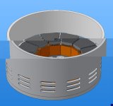
There's a lot of space left. 
......... in the middle, for the fan and bearingsTylerDurden said:There's a lot of space left.
")
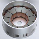
Assuming I actually build this design, I need to optimise the ratio of iron to copper. As I'm not interested in anything other than continuous torque, perhaps the way to go is to limit the amps to this level at the motor end and reduce the iron volume until it reaches saturation just beyond this point? Does this make sense?liveforphysics said:Wouldn't this design have a pretty poor copper fill percentage due to the inner diameter to outer diameter difference in available space for windings?
HAL9000v2.0
10 kW
Nice start Miles,
Just a question: Why didn't you make coils trapezoid also ? With round edges will be fine..
Just a question: Why didn't you make coils trapezoid also ? With round edges will be fine..
Hi Hal.
It would mean substantially more machining. This way, you just need to trim the edges with a cut-off saw. If you want anything other than a parallel inner core, I think you might as well machine the whole thing from a laminated blank.
It would mean substantially more machining. This way, you just need to trim the edges with a cut-off saw. If you want anything other than a parallel inner core, I think you might as well machine the whole thing from a laminated blank.
liveforphysics
100 TW
I'm all ready shopping for a 4th axis for my mill Miles. It would be my pleasure to machine whatever parts I'm capable of making for you.
That's very generous of you, Luke. I think it will be a while before I'm certain enough about this to start having metal cut, though... I've got a lot of learning to do
Are you planning to learn MCAD, to create the models to use in a CAM program? If you want any modelling done, to get you started, let me know.
Are you planning to learn MCAD, to create the models to use in a CAM program? If you want any modelling done, to get you started, let me know.
liveforphysics
100 TW
Miles said:That's very generous of you, Luke. I think it will be a while before I'm certain enough about this to start having metal cut, though... I've got a lot of learning to do
Are you planning to learn MCAD, to create the models to use in a CAM program? If you want any modelling done, to get you started, let me know.
Thanks Miles. I'm working with Rhino, and some other things. Mach3 is the software the CNC machine is being controlled with. Anything you want to send me that can be imported into these things sounds great to me.
Rhino is a great program but, it would probably be better to use a parametric modeller for things like motor/drive-train design.
Mind you, they've made a start in that direction: http://rhinocentre.blogspot.com/2009/02/rhino-goes-parametric-with-grasshopper.html
Mind you, they've made a start in that direction: http://rhinocentre.blogspot.com/2009/02/rhino-goes-parametric-with-grasshopper.html
lawsonuw
1 kW
IMHO I'd use an angular contact ball bearing to take the thrust loads and an outboard deep grove ball bearing to stabilize the shaft. www.skf.com has some rather nice calculators for bearing life in addition to a decent online catalog. The angular contact ball bearings can take nearly as much thrust loading as a tapered roller bearing and have lower friction. Might also look at the double row angular contact bearings. A bit spendy but they'll fully support the shaft with just one bearing.
Lawson
Lawson
liveforphysics
100 TW
Miles- Are you concerned about having a thin airgap in your back-iron? Wouldn't this mean needing thicker back-iron for a given flux density on the coil?
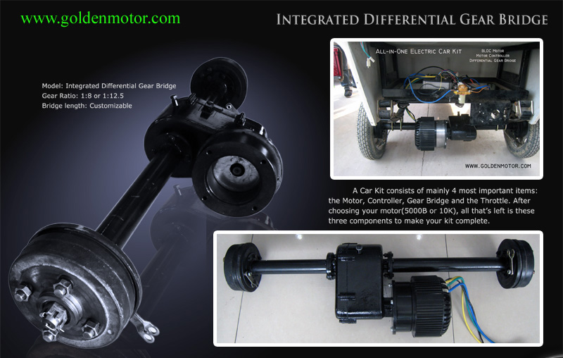
Your design seems similar to a refined version of the 5kw golden motor. It would be interesting to take a look again at how they did the stator lams in that single rotor axial design.
Your design seems similar to a refined version of the 5kw golden motor. It would be interesting to take a look again at how they did the stator lams in that single rotor axial design.
You mean the butt joint between the individual cores? Yes, I'm not sure how much impact this will have. I'll certainly lap the surfaces to get as good a contact as possible.liveforphysics said:Miles- Are you concerned about having a thin airgap in your back-iron?
Are there any photos of the inside of the 5kW Golden motor?
Thanks lawson, I'll look into this.lawsonuw said:IMHO I'd use an angular contact ball bearing to take the thrust loads and an outboard deep grove ball bearing to stabilize the shaft. http://www.skf.com has some rather nice calculators for bearing life in addition to a decent online catalog. The angular contact ball bearings can take nearly as much thrust loading as a tapered roller bearing and have lower friction. Might also look at the double row angular contact bearings. A bit spendy but they'll fully support the shaft with just one bearing.
Maybe a deep groove radial bearing at the pulley end of the shaft and an angular contact bearing at the other end?
liveforphysics
100 TW
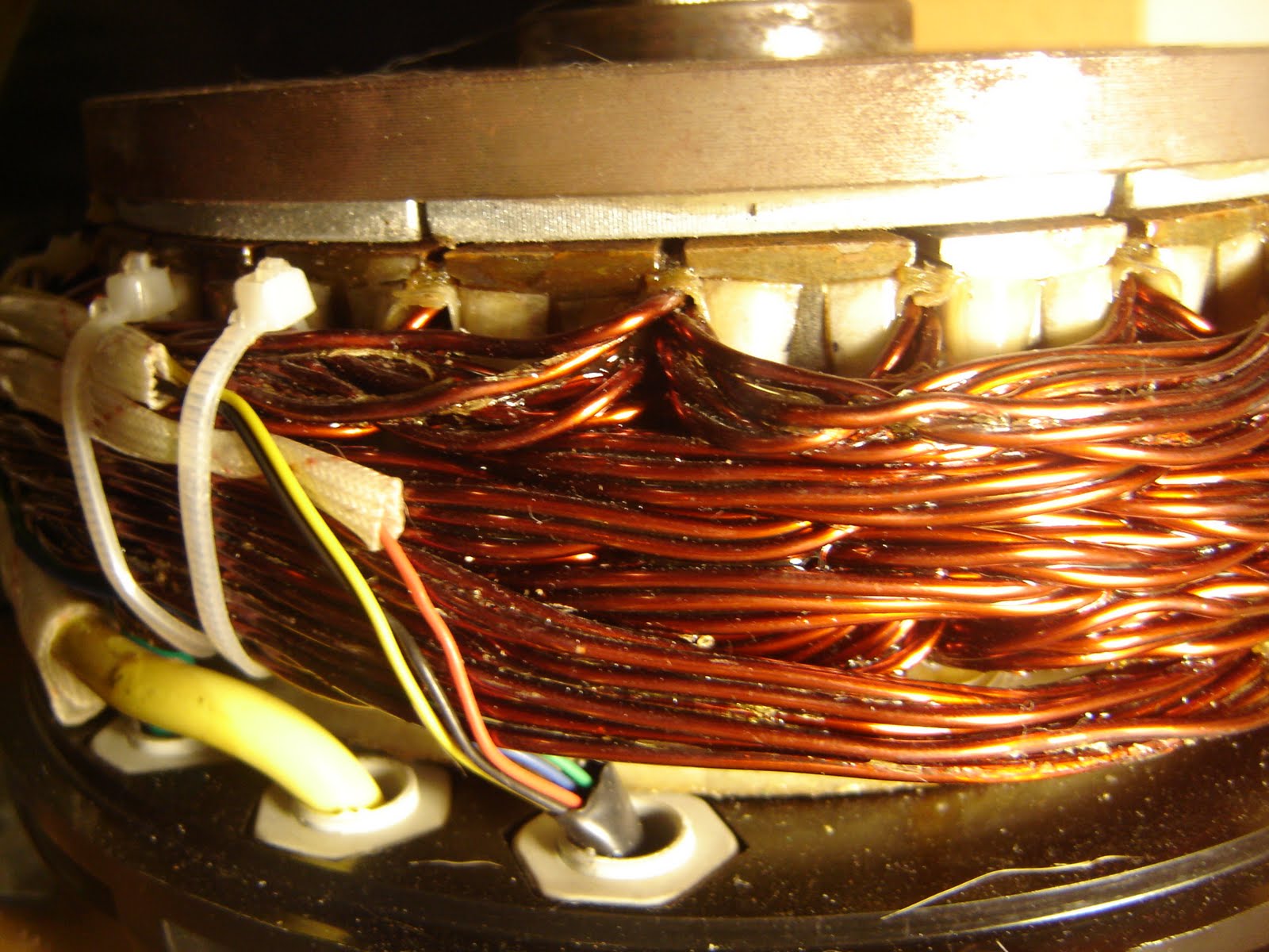
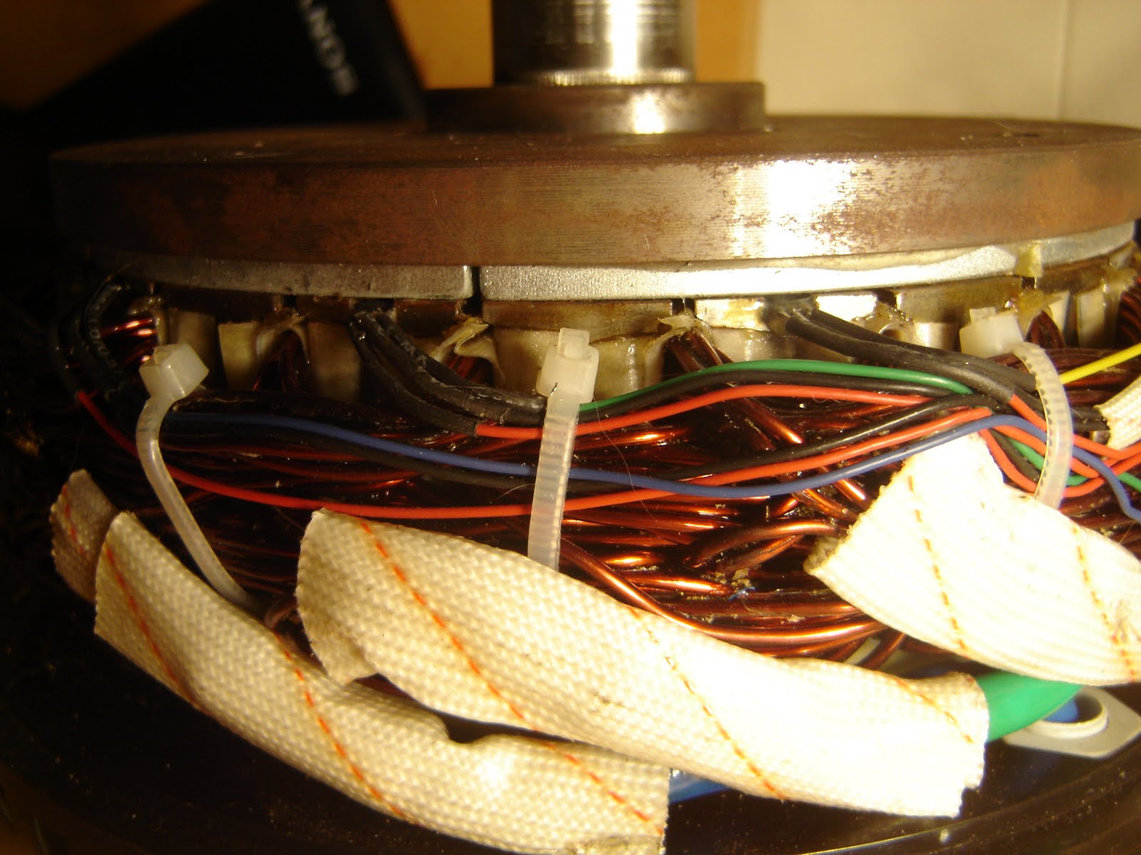
Miles said:Are there any photos of the inside of the 5kW Golden motor?
Here are a few from the ES member gestalt. The pics don't reveal much of how the stator lams were done.
Here is a pic in application:
liveforphysics
100 TW
It would appear they've got loads of lam's stacked on the backside of the magnets, and that the stator cores themselves are maybe ferrite?
liveforphysics
100 TW
Miles said:Thanks.
Crikey!
I think that's just machining marks on the magnet back-plate.
On the first photo you can just about see the laminations running across the cores?
Looking at it again, I agree those are machining marks.
I don't know about seeing the lams, maybe it's just my crappy moniter at work, but it doesn't show too much to me.
If you view the full sized image, you can see a very substantial amount of end-turn material. It also appears to be doing the 3 stator poles tied together winding method if I'm seeing things correctly. They are claimed to do 5kw at 85% efficiency, which is pretty impressive for the price compared to other options. I should hope to see anything you make in at least the low-mid 90% efficiency range
Is the whole appeal to the tied together stator pole winding groups just for the ease of magnet layout design? What is the attraction? I see it in the Astros as well, and it just seems like a lame way to go, but maybe I'm missing the advantages?
lawsonuw
1 kW
Miles said:Maybe a deep groove radial bearing at the pulley end of the shaft and an angular contact bearing at the other end?
Exactly what I was thinking. (btw "deep grove ball bearings" is a more technical name for the plane ball bearings found in everything)
For a commercial axial air gap motor, I'd expect it to use a single spiral lamination wound into a disk with the winding slots pre-cut in precisely the right spots. A pain to DIY but fast in production.
Another trick axial flux motors can pull easily is mechanical field weakening, i.e. an adjustable air gap. Would be useful for a single speed drive system.
Lawson
Very cool. I was wondering wouldnt you be able to just wrap your core material then machine it the way you want. Oh man the wheels are turning. To many projects but this one is stuck with me. Unfortunatly I will build something that may not be alowed in the contest but will have great potential in the ebike world. Just gathering thoughs as of right now, but I am excited to see some of the smartest guys on the forum to be builing this.
lawsonuw said:For a commercial axial air gap motor, I'd expect it to use a single spiral lamination wound into a disk with the winding slots pre-cut in precisely the right spots. A pain to DIY but fast in production.
I did consider whether or not it would be possible with post machining but, it would be too difficult to create teeth with such a small diameter core, I think.Arlo1 said:I was wondering wouldnt you be able to just wrap your core material then machine it the way you want.
An advantage of doing it as individual cores is that it leaves open the possibility of winding before assembly. Whether or not that will be the way to go is still not clear, though....
Another reason for picking the single rotor/single stator AF design is that it would easily allow experimentation with different rotors...lawsonuw said:Another trick axial flux motors can pull easily is mechanical field weakening, i.e. an adjustable air gap. Would be useful for a single speed drive system.
gestalt
10 kW
Miles,
Love the design, it is quite the sekks. Now that I'm better with the whole reasembly proccess I would be happy to take any pictures you would like of the insides of my motor with some better lighting and a better camera.
Love the design, it is quite the sekks. Now that I'm better with the whole reasembly proccess I would be happy to take any pictures you would like of the insides of my motor with some better lighting and a better camera.
Similar threads
- Replies
- 9
- Views
- 1,063
- Replies
- 2
- Views
- 160