Greetings people.
A set of performance plots for the MP2.
Results are based on the latest MESC firmware build with field weakening. Firmware used for testing was developend by
@mxlemming and is available here [
LINK] . MESC documentation is available [
HERE], questions about firmware operation should be referred to
@mxlemming. We tried several field weakening values for parameterization and 90 was selected for plotting. Data for these plots can be found at github release [Github:
9b2d6f5] in the "datasets" reprository. Plots are generated using matplotlib in python.
Data is collected by exporting serial information off of the F405 pill using the MESC serial. Briefly, this involves reconfiguring the MESC code to use UART1, connecting an ESP32 board to the UART1 pins, and sending data via bluetooth to a smartphone. The MESC code establishes a terminal with smartphone using "Another Term", a very nice vt100 emulator for androids. To get json output from the MP2 type: "status json" in the terminal. To complete logging data type "status stop". All the values that can be set using the terminal are displayed with "get". Values can be set using the command "set value number" so for example to set field weakening current type "set fw_curr 90".
Some settings in the code are as follows:
#define MAX_IQ_REQUEST 200.0f
#define ABS_MAX_BUS_VOLTAGE 80.0f
#define QS165 // I think this no longer matters
#define MIN_IQ_REQUEST 0
curr_max was set to 300 in the MESC terminal.
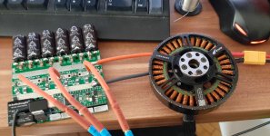
The motor used for testing: QS165, V1.0. The MOSFETs for the MP2: IPP026N10NF2S. Bike platform is shown here [
LINK]. The overall gear ratio is 9.8, the bike has 26 inch wheels, and to convert ehz to MPH divide by 13.996.
Max speed for today was 54 MPH or 87 KPH. During testing I was never able to get the MP2 temperature to raise to a noticeable level -- probably as a result a big heat sink plate that gets a lot of airflow on the bike. The specific branch of the MESC firmware used for testing is here: [
LINK].
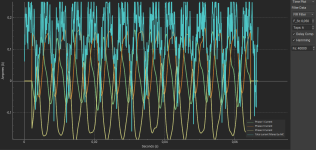
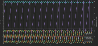
Values shown in the plots refer in part to Id and Iq, which are important mathematical values relating to the amperages applied to the d-axis and q-axis of the motor. One relationship between these amperages is that phase Amps = sqrt( (iq^2) + (id^2) ), described by "phase A" in the plots. Other values plotted are:
- ehz = RPM / polepairs
- iq = Iq, explained above
- -id = the inverse of Id
- iqreq = iq "requested" by the user based on turning the throttle
- vbus = Battery voltage
- Vd = voltage vector associated with the d-axis
- Vq = voltage vector associated with the q-axis
Logs were collected under two conditions: 1) flat ground with one turn of the throttle, and 2) on a paved path with 20-30 percent grade with three pulses on the throttle. Samples are collected at 10hz. Note y-scales for ehz, vbus, vd and vq are all different.
Enjoy.
View attachment 334401
View attachment 334402
View attachment 334403
Many thanks to
@mxlemming for his patient guidance and the MESC code,
@badgineer for the MP2 platform, and
@netzpfuscher for the incredible MESC terminal!