Motor chatter/stumble from stop

Caprisvo

1 mW
Joined
Mar 17, 2023
Messages
10
Location
Salem
Hello all, new here and looking for a little help/advice on direction to go with my current problem (apologies in advance for length of post).

I ran into a package deal on some used components online locally and got a package deal that included a couple Bafang 48v 750w rear hub motors.
Both had pulled/damaged wires and needed repair, but otherwise appear in near new condition with no signs of overheating or anything.

I've repaired one so far. I was able remove the damaged section of wire and have enough wire left to feed them back into the hub and resolder them in to the circuit board on the motor.
Ran it with the controller and throttle I planned to use on the bench and everything seemed great.

Laced the motor into the rim, and converted the bike.

Once everything was buttoned up, testing in the garage with wheel elevated, everything was still all good.
Smooth ramp up and smooth quiet running at all speeds.

Hop on for ride, and engaging the throttle from stop or low speed results in clunky motor chattering.
If I peddle and get a little speed going and then engage the throttle the bike performs as expected, and the motor is smooth and quiet.
As long as I have some speed going I can engage/disengage/re-engage the throttle with normal results/bike responds problem free.

Here are my components
Motor: Bafang rear hub "BF RMG06 48V750W(7)"
Controller: Brainpower 866-15
LCD display: s866 (sold as a package with controller)
Battery: Reention Polly DP-2170-5 48V 20AH 960WH for 1000W (new, known good)
Thumb throttle: TT-009

After some internet scouring I found a couple posts with people describing similar problems, but nothing concrete for a solution.

I found one thread that suggested hall sensor(s) issues that were overcome/nullified once some rotational speed was attained prior to engaging the throttle.

As that seemed to most closely match my issue I tested all three.
I believe my testing procedure is correct.
With all wiring and components still installed on the bike, and the wheel propped up I turned the power on at the controller and measured between the black wire and each hall sensor wire individually, slowly rotating the wheel in reverse.
All sensors measure 4.86v constantly, and don't appear to be cycling.

My questions.
1. With the wire damage history on the motor, is it likely that all hall sensors are bad?
2. When a hall sensor goes bad, does it just not cycle and read constant voltage, or more typically read consistent 0V?
3. Am I on the right track chasing "bad" hall sensors, or is there some other circuitry that could cause them not to cycle?

Thanks in advance for any help and advice!
 
Last edited:
Hello all, new here and looking for a little help/advice on direction to go with my current problem (apologies in advance for length of post).

I ran into a package deal on some used components online locally and got a package deal that included a couple Bafang 48v 750w rear hub motors.
Both had pulled/damaged wires and needed repair, but otherwise appear in near new condition with no signs of overheating or anything.

I've repaired one so far. I was able remove the damaged section of wire and have enough wire left to feed them back into the hub and resolder them in to the circuit board on the motor.
Ran it with the controller and throttle I planned to use on the bench and everything seemed great.

Laced the motor into the rim, and converted the bike.

Once everything was buttoned up, testing in the garage with wheel elevated, everything was still all good.
Smooth ramp up and smooth quiet running at all speeds.

Hop on for ride, and engaging the throttle from stop or low speed results in clunky motor chattering.
If I peddle and get a little speed going and then engage the throttle the bike performs as expected, and the motor is smooth and quiet.
As long as I have some speed going I can engage/disengage/re-engage the throttle with normal results/bike responds problem free.

Here are my components
Motor: Bafang rear hub "BF RMG06 48V750W(7)"
Controller: Brainpower 866-15
LCD display: s866 (sold as a package with controller)
Battery: Reention Polly DP-2170-5 48V 20AH 960WH for 1000W (new, known good)
Thumb throttle: TT-009

After some internet scouring I found a couple posts with people describing similar problems, but nothing concrete for a solution.

I found one thread that suggested hall sensor(s) issues that were overcome/nullified once some rotational speed was attained prior to engaging the throttle.

As that seemed to most closely match my issue I tested all three.
I believe my testing procedure is correct.
With all wiring and components still installed on the bike, and the wheel propped up I turned the power on at the controller and measured between the black wire and each hall sensor wire individually, slowly rotating the wheel in reverse.
All sensors measure 4.86v constantly, and don't appear to be cycling.

My questions.
1. With the wire damage history on the motor, is it likely that all hall sensors are bad?
2. When a hall sensor goes bad, does it just not cycle and read constant voltage, or more typically read consistent 0V?
3. Am I on the right track chasing "bad" hall sensors, or is there some other circuitry that could cause them not to cycle?

Thanks in advance for any help and advice!
Based on your questions, does this mean you didn't test the sensors while you had the motor open? If not, here's the method to test without disassembly.

A lot of those Brainpower controllers are dual mode, and if so, and the halls are bad, then the controller will default to sensorless operation, which is less smooth from the start. Replacing the sensors is fairly easy, especially since you are already comfortable with opening the motor.
 
Thanks for the reply.

I did not test with the motor open. Didn't know to, or suspect anything other than compromised wire was wrong.

I tested the hall sensors exactly like the video, and they show constant 4.86v when slowly turning the wheel backwards.

I couldn't find much for specs on my specific model of controller to tell if it is dual mode or not.

I did get some hall sensors off of amazon, they should arrive today. Hoping they are the correct ones?:
They’ll probability work. The Honeywell SS41 is what’s recommended (the ones Grin sells), but the SS41F has similar specs. You can probably do a search on the forum and find some info, but my guess is they’ll work.
 
*Update*
I completely disconnected the hall sensor connector and tested the bike.

It tests exactly the same in the garage with wheel propped up, and same chatter from stop and low speed when riding.

Not sure if this tells anything other than the controller operates sensorless also.
 
Okely-dokely...

Referencing the hall sensor test methods outlined here:
Testing BLDC motor's Phase Wiring - Hall Sensors and Wiring. - Electricbike.com Ebike Forum

I retested the hall sensors both on the bike with all wiring hooked up and controller powered on.
Still see no hall sensor toggling.
5v all the time

I pulled the wheel and bench tested it connected to a 5v power source/resister.
All three hall sensors toggled on and off as they should.

Would this seem to indicate the new controller is defective?
brainpower.png
 
Last edited:
On the controller side of the plug?

I'll have to put some things back together tonight to test that. Currently have the hub motor opened up.

If they are all 5v, testing on the controller side of the unhooked hall connector is that proof that controller is borked, or maybe one of the settings not right?
 
Last edited:
All wiring hooked back up with the exception of the hall sensor plug from controller to motor.
Blue, green, yellow hall wires on the controller side of the plug all measure 5v.
 
You can only test the hall sensors on the side of the connector that they are on (motor side). ;)

The only thing you can test on the controller side is whether or not you get 5v on the pullups at the three signal lines (you should), and whether or not you get the 5v power supply to run the halls. If you get those, then that part is working, but you would need access to a data display of what the MCU itself sees to know if the controller is actually reading the signals from the motor or not. Some advanced controllers' setup software allows this, but I know of no such software for xunlida / brainpower controllers (they're "dumb" controllers).


If the halls all work when not connected to the controller, but are connected to 5v power *and* a pullup resistor to 5v on the signal line, there's no reason I can think of for them to not work when correctly connected to the controller.


If the system operates identically with the halls disconnected or connected, and the halls do work correctly at the connector, and the controller side of the connector reads 5v on the right places without them connected (proving it doesn't have a broken wire/etc), then the most likely thing is that the controller is only running in sensorless mode (even though it has a hall connector). I have a generic controller that is like that--has a hall connector but it never does anything with the signals.
 
Last edited:
I may have misunderstood what E-HP was asking me to check

With the hall connector plug disconnected, measuring voltages on the controller side of the plug using the black wire for ground I get 5v on red, blue, green, yellow, and white wires. Actual is 4.65v on red, 4.96v on all others.

This explains to me why the hall sensor check with all wiring connected/controller powered on showed the sensors not cycling when the wheel was turned and powered up constantly.

I am nowhere near an expert, (in fact typically know just enough to be dangerous ;)), but I feel like the red wire should be suppling 5v to the halls, the hall sensors sending 5v or lack of it back to the controller via the b/g/y hall wires depending on their location relative to magnets, and the controller shouldn't be sending power through b/g/y wires to the hall sensors.

If the controller is running in sensorless mode regardless of hall sensor lines being hooked up, does that cause/explain the low speed chattering?

I have the basic settings on the S866 display set up (voltage/wheel size/throttle vs PAS) but there quiet a few I don't even understand on the Chinese to English translated setting instructions.
Could one setting be to run sensorless or not?
 
With the hall connector plug disconnected, measuring voltages on the controller side of the plug using the black wire for ground I get 5v on red, blue, green, yellow, and white wires. Actual is 4.65v on red, 4.96v on all others.

That's normal, so that part is working as expected.

The controller has internal pullup resistors on each of the signal wires, whcih go to a slightly higher voltage than that seen on the supply line. The supply line usually has a diode in it which drops the voltage there a tiny bit (the diode is there to try to prevent backfeed of the phase voltages into the 5v regulator in the event of a wiring-damage short (too common, especially in hubmotors without torque arms), along with induced voltage spikes in high-current situations).


This explains to me why the hall sensor check with all wiring connected/controller powered on showed the sensors not cycling when the wheel was turned and powered up constantly.
It doesn't, actually. The 5v on those lines is required for the hall sensors to operate correctly and provide signals. (they won't provide valid signals without pullups on their signal lines, for any of the typical halls used in typical motors).

I am nowhere near an expert, (in fact typically know just enough to be dangerous ;)), but I feel like the red wire should be suppling 5v to the halls, the hall sensors sending 5v or lack of it back to the controller via the b/g/y hall wires depending on their location relative to magnets, and the controller shouldn't be sending power through b/g/y wires to the hall sensors.
The hall sensors actually only ground that 5v the controller has on the signal lines, whenever the halls are active (turned on). They don't have circuitry to output any voltage, just to ground what's placed on their outputs. (called Open Collector).

Most (UVW) hall sensors in most motors are "bipolar latching" so they change state only when the polarity of the magnetic field changes (so as every other magnet passes them).


If the controller is running in sensorless mode regardless of hall sensor lines being hooked up, does that cause/explain the low speed chattering?
It can--most controllers are terrible at figuring out where the motor is actually at until it's spinning fast enough to generate a lot of BEMF voltage, which is why they use the hall sensors to do that job. ;)

(there are controllers using FOC that do a great job sensorless, but they are generally much more expensive than the typical controllers, which also don't do FOC (which is just an advanced method of modulating the motor current)

I have the basic settings on the S866 display set up (voltage/wheel size/throttle vs PAS) but there quiet a few I don't even understand on the Chinese to English translated setting instructions.
Could one setting be to run sensorless or not?

There are some controllers/displays that have options for what modes they use; I don't know if the XL / BP controllers do. There are a few threads about them, but I don't know if they have this info in them.

There was a thread about (I think) a KT controller / display combo that has a specific setting for whether it always runs sensorless, always sensored, or autodetects.
 
The hall sensors actually only ground that 5v the controller has on the signal lines, whenever the halls are active (turned on). They don't have circuitry to output any voltage, just to ground what's placed on their outputs. (called Open Collector).
This seems to be odd behavior, since on the bench, the halls go from 5V to 0V when rotating the wheel, but when connected they can't bring the 5V to 0V.
 
So far whenever this has been reported (that I can recall reading here), it turned out later that the testing with controller connected didn't have valid results due to connection problems either between motor and controller (especially a bad ground), or the testing equipment itself.

The only other reason I can think of is if the pullup resistors in the controller were all shorted to 5v at the signal lines--this would short all the hall signals together, and leave nothing to drop the votlage across during the hall activation (grounding), except the internals of the hall itself (which leaves the output at signal voltage, instead of ground).

There are probably other possible causes, but knowing how the hall signals are typically wired in both motor and controller, that's all I can think of.
 
I know the wire connection in the hub is golden, and the connection at the hall connector to the controller is solid. The push together main harness connection between would be the only spot I have no to way to verify. Visually looking in the plug ends everything looks OK.

Wish now when I had it apart earlier I'd done a continuity test to rule that out...
I might before throwing in the towel and buy a different controller.

I did find a Youtube video on setting for the S866 LCD, and there was a setting for amps. Default was 12a. I set it for the max of 22a. Will try and get a test tomorrow to see if there is any change.

Appreciate the help so far!
One thing you might check is that if the halls use those molex connectors with the blade style pins, check carefully that the blade for the ground wire is not bent or backing out. If the ground isn't making it to the halls, then they won't be pulling the 5V to ground when the controller is connected to the motor and rotating the wheel.
 
Ground is good at molex connector.
The main connector could possibly have a issue I guess. I'd have to pull the lid of the hub motor again to verify it and all other signals are in fact making it to the motor.

No change from the amp setting change.

I'm not really sure what to call what it is doing at lower speed or from a standing stop. "chatter/stumble" is the best I could come up with.
Throttle doesn't successfully move the bike until once you've reached a certain speed peddling, and then it smooth clean acceleration. Bike performs very well from that speed to full speed.
I can tell the throttle is doing trying to do something prior to peddling up to the all good speed. You can feel it engage the motor, and then drop power out, kind of stuttering power, but not successfully propelling the bike forward.
 
So far whenever this has been reported (that I can recall reading here), it turned out later that the testing with controller connected didn't have valid results due to connection problems either between motor and controller (especially a bad ground), or the testing equipment itself.
Validation time. It was a bad ground. Didn't suspect the connector between the controller and motor, as I'd looked at it several times. Turns out under closer inspection the ground connector tab was damaged.

I had a ground on both sides of the molex connector, but it wasn't making it through the motor cable connector.
1680143276379.png
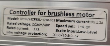
The resolution was a bit longer path than that. Actually discovered it after installing another controller I acquired in a parts lot purchase (a KT) and had incapability issues with the display.

At any rate, I patched in a new connector and all is well. I wouldn't have probably every found the connector issues without the help, suggestions here, and the odd situation of the halls bench testing good but not switching while wired to controller and on the bike, so thank you for the help.

The KT controller I ended up with was one I wanted to use originally, but as it was a spare for a Sondors bike, had a wiring oddity that led me to believe it was bad initially. Ran into a post online on someone who'd hacked the julet wiring harness connecting a specific wire to power the controller.

1680144563001.jpeg
 
Back
Top