Motor Controller with Customizable Electronics, easy DIY and repair OpenSource

flute2k3@hotmail.com said:
do you think it could be the driver polarity difference
It is different, yes, but I set the low side PWM polarity to inverted already. PWM works, open loop run works also, but the phase current is not measured properly obviously. Regular ADC works, injected ADC seems to be the problem.

regards
stancecoke
 
Forum message on SimpleFOC forum, about the EasyDIY ESC: https://community.simplefoc.com/t/ebike-escooter-motor-controller-easy-to-diy-build-and-repair-with-room-for-custom-electronics-board/1500/18
 
Hi

flute2k3@hotmail.com said:
what I can see from the pin mapping is, you can not simply spin the motor without modifying the v2 or v3 firmware since they are all based on m365 hardware, would like to see a tuition on how to modify and compile the v2 or v3 to make it work.

As v3 has already been discussed a bit, I'll add some notes on v2 compatibility.

v2 needs the hall sensor signals on pins with timer. The pins used by this version (EasyDIY v0.5) do not have timer! So adapting EBiCS v2 software is not a simple affair.
What can be done though is to short the pins that get the hall sensor signals to the pins that should get them in v2 pinout.
And then v2 should be usable!
The "original" pins from our EasyDIY v0.5 need to be set to floating in that case so not to interfere with the signal.
I discussed this in the telegram channel(group?) also with stancecoke and mxlemming, and most ideeas for v2 i have from them.

I also pondered making the pins that get the hall sensors configurable in hardware via jumpers, but I thought of it late in the design, when major redesign would have been necessary, and space also seemed insufficient. So I chose to finish the board as is, and do the pin shorting instead for v2 compatibility.

PS: if you're asking yourself why we did not go for the v2 compatible pinout form the beginning, the reason is it would have blocked a useful pin (I think it was a UART or CAN). The EasyDIY ESC v0.5 with current pinout leaves all UART and all CAN pins open for usage via the expansion header, so it is optimized for flexibility.

Br,
 
Hi

Woly said:
All the more reason to switch to the black pill. According to hacakaday, it's now hard to get a blue pill with a genuine ST chip and if any of the FOC code is based on ST libraries, they are not licensed to use on counterfeit chips.

Just a bit of info on the black vs blue pill decision:

We went with bluepill because of 2 big reasons.
1) EBiCS v2 and v3 was already set up for this chip! This was by far the main reason.
2) Blackpill does not have any CAN.

Personally I would have loved to use the blackpill, seemed more future-proof to me, and better in many many ways, but I don't have the skill (and time) to write/adapt the code to blackpill. So this was a software-driven decision.
If the software wizards decide to port to blackpill, or some other better widely available devboard, I'd be happy to start working on the next version :)
Hope to have some lessons learned from 0.5 by then.

Br,
 
Woly said:
All the more reason to switch to the black pill. According to hacakaday, it's now hard to get a blue pill with a genuine ST chip and if any of the FOC code is based on ST libraries, they are not licensed to use on counterfeit chips.

IIUC, v3 doesn't use ST code, if so, it would be okay to use on counterfeit ones w.r.t licensing.

badgineer said:
:
1) EBiCS v2 and v3 was already set up for this chip! This was by far the main reason.
:

v2 (when checked a while ago) uses a mix of code using ST license & GPLv3. Per my understanding, the clauses in those licenses do not allow mixing source files with these licenses, but feel free to ignore my opinion.

badgineer said:
Personally I would have loved to use the blackpill, seemed more future-proof to me, and better in many many ways, but I don't have the skill (and time) to write/adapt the code to blackpill. So this was a software-driven decision.

FOC conventionally does (for correctness) simultaneous sampling of 2 phase currents, this can't be achieved with black pill as it has only one ADC instance.
 
I made a simple board based on v0.1 but changed hall inputs A, B from A11, A12 to B4, B5, to be in line with M365 original pin mapping, I'm running v2 firmware, so I can connect to PC and control by keyboard as V2 introduced.

The issue is, when the board energized, it spins automatically after a few second around 65 rpm. I expect it shall standby and waiting for command from keyboard.

when I connect PC via uart, I can control, but this auto-spin issue puzzled me, anyone knows what could be the issue? and where is the codes I shall look at?
 
flute2k3@hotmail.com said:
I made a simple board based on v0.1 hardware, and running v2 firmware, the good thing is I can connect to PC and control by keyboard as V2 introduced.

The issue is, when the board energized, it spins automatically after a few second around 65 rpm. I expect it shall standby and waiting for command from keyboard.

when I connect PC via uart, I can control, but this auto-spin issue puzzled me, anyone knows what could be the issue? and where is the codes I shall look at?
For V2 firmware, you should ask your questions on the Telegram channel specific to it, although I do not know how to access it, since it seems private, needs an invitation or such.
 
flute2k3@hotmail.com said:
well... I like very much to join, but I can't due to some reason, it's a pity.
Seems to me that V2 developers are only there and not here, so I think you will be alone.
 
flute2k3@hotmail.com said:
I made a simple board based on v0.1 but changed hall inputs A, B from A11, A12 to B4, B5, to be in line with M365 original pin mapping, I'm running v2 firmware, so I can connect to PC and control by keyboard as V2 introduced.

The issue is, when the board energized, it spins automatically after a few second around 65 rpm. I expect it shall standby and waiting for command from keyboard.

Hi.

How does your board look like? did you do any serious redesign or did you reuse most of the v0.1 layout?
v0.1 did not have the best design (including 2 "bugs") and was quite noisy as a result (casainho tells me).
And yeah, when you have a hammer every problem looks like a nail - so the fact i only know a tiny bit of hardware design and zero software makes me ask about the hardware :)

About the software - the EBiCS v2 is VESC tool compatible afaik - doesn't that have some debug features ?

Br,
 
Hi.

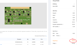
Is anybody from the EU area interested in a group order? I'd be interested in participating (but not organizing :D)

A boards with the SMT side assembled at jlcpcb would be 57$ for 5 boards, so ~12$ a piece. I only need 1, so it's hardly a good idea to order 5. And I haven't got the time to hand solder a whole board, which would be the cheap version.

Order_Cost.png

Br,
 
badgineer said:
Hi.

How does your board look like? did you do any serious redesign or did you reuse most of the v0.1 layout?
v0.1 did not have the best design (including 2 "bugs") and was quite noisy as a result (casainho tells me).
And yeah, when you have a hammer every problem looks like a nail - so the fact i only know a tiny bit of hardware design and zero software makes me ask about the hardware :)

About the software - the EBiCS v2 is VESC tool compatible afaik - doesn't that have some debug features ?

Br,

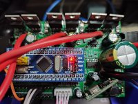
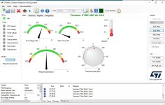
here is my board, 1648293269690.jpgI modified DC/DC module, others keeps almost the same, with two bugs fixed. I use automatic routing so PCB could be bad as v0.1. however if I use ST motor control work bench compile a simply firmware, there is no such issue, only when I push start button it spins, even good start at 25 rpm. if I start from zero speed, it does not spin, with absorb 20 mA more current only - by this I deduce the problem could not be hardware.
MC.JPG

I changed current sensing resistor from 0.01 to 0.002, because it did not work well.
some interesting finding, it works exact the same/no notable difference if:
* remove C7, C16, C62
* change the connection of C40 & C62, C5 & C7, C15 & C16 to VBAT and GND

I think the issue could be on coding rather than hardware or PCB layout.
 
@casainho
maybe you can try to test your v0.1 board on hand, and see if we experience the same issue.

I'm checking the v2 codes now, not sure if it detect the emf as well, v0.1 board has no emf feedback but M365 does.
 
flute2k3@hotmail.com said:
@casainho
maybe you can try to test your v0.1 board on hand, and see if we experience the same issue.

I'm checking the v2 codes now, not sure if it detect the emf as well, v0.1 board has no emf feedback but M365 does.
I do not have free time. My plan on this project is to build the new version on the board. The firmware V3, my plan is to keep developing it only for the needs I will have to use in my M365 EScooter, and probably use this board there later.
 
flute2k3@hotmail.com said:
Here is my board,

So you did quite a bit of redesign as far as I can see - so the v0.1 problems might not apply :)

flute2k3@hotmail.com said:
I changed current sensing resistor from 0.01 to 0.002, because it did not work well.
good, i also changed them to 0.001 on v0.5, that really needed to be changed. On M365 they're 0.002, so fit better to the standard Opamp gain.

flute2k3@hotmail.com said:
some interesting finding, it works exact the same/no notable difference if:
* remove C7, C16, C62
* change the connection of C40 & C62, C5 & C7, C15 & C16 to VBAT and GND

Capacitors are increasingly important with rising current / power draw. At very low current, they don't make such a big difference.
But they will make your life harder if they're not connected to GND (but to the shunt) as soon as you actually use some power.

Can't comment on auto-route though, and can't help with the software :(

flute2k3@hotmail.com said:
I modified DC/DC module,..

What 12V module did you use?

Br,
 
Hi Afzal

afzal said:
FOC conventionally does (for correctness) simultaneous sampling of 2 phase currents, this can't be achieved with black pill as it has only one ADC instance.

Isn't it enough if the 2 samples are taken near-simultaneously, as in in very quick succession, for practical purposes?
I mean surely, if you have a theoretical system with infinitely fast sampling rate, and sample the 2 phases increasingly close to each other, at some point, for foc, there difference to simultaneous samples disappears completely.

The question is then - how small does the time difference between the 2 samples need to be, to be good enough for foc?

I'm asking because the blackpill uC can sample quite fast - 2.4 Msps. Isn't this maybe enough?

Hope it's more or less understandable what I'm trying to say - and not very stupid :D

Thanks and Br,
 
I temporarily give up on v2 and shift to v3, I follow the instruction here: https://github.com/OpenSourceEBike/TSDZ2_wireless/blob/master/EBike_wireless_remote/documentation/development-flash_and_debug_firmware.md
however since I use win10, very difficult to make it work, missing path/file here and there. I then shift to "stancecoke" version - v0.5 branch of v3, connect a hall throttle to pin A1, of cos +5V and GND as well, but it does not work at all when energized, not sure what is the issue. in order to walk around my DC/DC with no EN pin, I connect PC14 directly with +3.3V, so it shall be no problem and it does work well on v2.

@stancecoke, any hints for your v3 0.5b?
 
flute2k3@hotmail.com said:
I temporarily give up on v2 and shift to v3, I follow the instruction here: https://github.com/OpenSourceEBike/TSDZ2_wireless/blob/master/EBike_wireless_remote/documentation/development-flash_and_debug_firmware.md
however since I use win10, very difficult to make it work, missing path/file here and there. I then shift to "stancecoke" version - v0.5 branch of v3, connect a hall throttle to pin A1, of cos +5V and GND as well, but it does not work at all when energized, not sure what is the issue. in order to walk around my DC/DC with no EN pin, I connect PC14 directly with +3.3V, so it shall be no problem and it does work well on v2.

@stancecoke, any hints for your v3 0.5b?
Are you using the firmware to drive a M365?

If not, if you want to drive only a motor, try the modular EBiCS_motor_FOC -- see the example folder that has simple working example: https://github.com/EBiCS/EBiCS_motor_FOC
 
casainho said:
Are you using the firmware to drive a M365?

If not, if you want to drive only a motor, try the modular EBiCS_motor_FOC -- see the example folder that has simple working example: https://github.com/EBiCS/EBiCS_motor_FOC

the problem is, I have trouble to compile it in VS code, I tried to compile in stm32cubeIDE but failed, this guy does not support submodule, all the instruction looks under linux instead of win10.
 
flute2k3@hotmail.com said:
the problem is, I have trouble to compile it in VS code, I tried to compile in stm32cubeIDE but failed, this guy does not support submodule, all the instruction looks under linux instead of win10.
Use the guide here: https://opensourceebike.github.io/development/development-flash_and_debug_firmware.html

You can build the code just by calling "make" on the command line, as explained on the guide.

Yes, there are no specific instructions for windows.
 
flute2k3@hotmail.com said:
@stancecoke, any hints for your v3 0.5b?

To activate the analog throttle in v3 0.5, you have to add a #define ADCTHROTTLE to the config.h or the main.h
The throttle has to be connected to PA7.

CubeMX%20Pinout.PNG


https://github.com/Koxx3/SmartESC_STM32_v3/blob/9fd39ae8955ebe9d6ee1927e6fceafeb81445952/Core/Src/main.c#L617

regards
stancecoke
 
stancecoke said:
To activate the analog throttle in v3 0.5, you have to add a #define ADCTHROTTLE to the config.h or the main.h
The throttle has to be connected to PA7.

per your instruction I add #define ADCTHROTTLE in config.h, however I get below error msg:

../Core/Src/main.c: In function 'main':
../Core/Src/main.c:619:73: error: 'MotorState_t' {aka 'struct <anonymous>'} has no member named 'phase_current_limit'
619 | MS.i_q_setpoint=map(ui16_reg_adc_value,THROTTLEOFFSET,THROTTLEMAX,0,MS.phase_current_limit);
| ^
make: *** [Core/Src/subdir.mk:55: Core/Src/main.o] Error 1
"make all" terminated with exit code 2. Build might be incomplete.


I'm using stm23cubeIDE
 
flute2k3@hotmail.com said:
stancecoke said:
To activate the analog throttle in v3 0.5, you have to add a #define ADCTHROTTLE to the config.h or the main.h
The throttle has to be connected to PA7.

per your instruction I add #define ADCTHROTTLE in config.h, however I get below error msg:

../Core/Src/main.c: In function 'main':
../Core/Src/main.c:619:73: error: 'MotorState_t' {aka 'struct <anonymous>'} has no member named 'phase_current_limit'
619 | MS.i_q_setpoint=map(ui16_reg_adc_value,THROTTLEOFFSET,THROTTLEMAX,0,MS.phase_current_limit);
| ^
make: *** [Core/Src/subdir.mk:55: Core/Src/main.o] Error 1
"make all" terminated with exit code 2. Build might be incomplete.


I'm using stm23cubeIDE
guess it was a typo, line 619 shall be
MS.i_q_setpoint=map(ui16_reg_adc_value,THROTTLEOFFSET,THROTTLEMAX,0,MP.phase_current_limit);
I move throttle to pin A7, but it still does not work. I see main.h line 74/75 defines a throttle on A1, what is it?
#define Throttle_Pin GPIO_PIN_1
#define Throttle_GPIO_Port GPIOA
 
flute2k3@hotmail.com said:
has no member named 'phase_current_limit'

I shifted this parameter to the motorparameter struct, without taking account, that it is used in the analog throttle option :). I've fixed it at gitub:

https://github.com/Koxx3/SmartESC_STM32_v3/commit/4bd351263779947dabdfd69c4bce9a643eabba9e

The throttle value (AIN7 on PA7) is read from position 1 (start counting from zero) of the regular ADC array:
https://github.com/Koxx3/SmartESC_STM32_v3/blob/4bd351263779947dabdfd69c4bce9a643eabba9e/Core/Src/main.c#L940

https://github.com/Koxx3/SmartESC_STM32_v3/blob/4bd351263779947dabdfd69c4bce9a643eabba9e/Core/Src/main.c#L1365

https://github.com/Koxx3/SmartESC_STM32_v3/blob/4bd351263779947dabdfd69c4bce9a643eabba9e/Core/Src/main.c#L248

If it still doesn't work, you will have to do logs in debug mode. Otherwise, it's poking around in the fog.
Of course you have to make sure, that there is no pullup or pulldown on PA7

regards
stancecoke
 
Back
Top