Motor Controller with Customizable Electronics, easy DIY and repair OpenSource

guess my ST-link is a fake one, stm32IED does not support it. thus I can't debug.

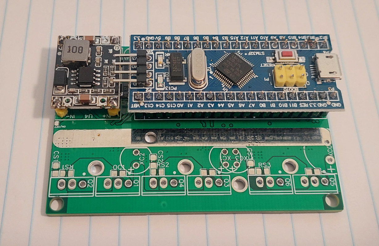
I checked variable voltage correctly applied on A7, the current consumption is very low, looks to me the driver is disabled, is there any checking points stopping the driver/motor? I changed the min voltage to 12V since my power supply is 28V, afraid there are low voltage protection function to shutdown the driver... any other else?
 
Ah, if you use a different driver, you have to invert the low side polarity perhaps.
https://github.com/Koxx3/SmartESC_STM32_v3/blob/4bd351263779947dabdfd69c4bce9a643eabba9e/Core/Src/main.c#L1062

Change here to
Code:
sConfigOC.OCNPolarity = TIM_OCNPOLARITY_LOW;

And of course there is a low voltage protection, just set it to a lower level in the config.h
https://github.com/Koxx3/SmartESC_STM32_v3/blob/4bd351263779947dabdfd69c4bce9a643eabba9e/Core/Inc/config.h#L70

regards
stancecoke
 
casainho said:
flute2k3@hotmail.com said:
the problem is, I have trouble to compile it in VS code, I tried to compile in stm32cubeIDE but failed, this guy does not support submodule, all the instruction looks under linux instead of win10.
Use the guide here: https://opensourceebike.github.io/development/development-flash_and_debug_firmware.html

You can build the code just by calling "make" on the command line, as explained on the guide.

Yes, there are no specific instructions for windows.

I installed a dedicated ubuntu for compiling this firmware and finally I am able to make it working. the strange thing is, I use the exact same setting in win10 but get make error, anyway good to have the motor humming, though not spinning. I guess it is hall angle, phase shift, etc setting not matching the default value.

could you guild me where of the file is the hall angle I need to look and modify? I can't find some obvious variables like similar using in MCSDK
#define HALL_PHASE_SHIFT
#define HALL_SENSORS_PLACEMENT

Thanks!
 
flute2k3@hotmail.com said:
casainho said:
flute2k3@hotmail.com said:
the problem is, I have trouble to compile it in VS code, I tried to compile in stm32cubeIDE but failed, this guy does not support submodule, all the instruction looks under linux instead of win10.
Use the guide here: https://opensourceebike.github.io/development/development-flash_and_debug_firmware.html

You can build the code just by calling "make" on the command line, as explained on the guide.

Yes, there are no specific instructions for windows.

I installed a dedicated ubuntu for compiling this firmware and finally I am able to make it working. the strange thing is, I use the exact same setting in win10 but get make error, anyway good to have the motor humming, though not spinning. I guess it is hall angle, phase shift, etc setting not matching the default value.

could you guild me where of the file is the hall angle I need to look and modify? I can't find some obvious variables like similar using in MCSDK
#define HALL_PHASE_SHIFT
#define HALL_SENSORS_PLACEMENT

Thanks!
Good!!

To be clear, which firmware are you using??
 
casainho said:
To be clear, which firmware are you using??

I use your example only, has nothing to do with v3, nor submodule. I can successfully build v3 with your submodule, but it does not work, let me start from the most simple version and check v3 later.
 
flute2k3@hotmail.com said:
casainho said:
To be clear, which firmware are you using??

I use your example only, has nothing to do with v3, nor submodule. I can successfully build v3 with your submodule, but it does not work, let me start from the most simple version and check v3 later.
Ok, that is a good idea as you just need to replicate what I did and because is a simple / small example, it should be a safe bet.

Which pins are you using, on init_motor(), that are different from the ones on the example??

The very first thing you need to do is the motor_autodetect() -- use the debugger, put a breakpoint on line 292 and 295. Make sure it goes to line 292 motor_autodetect():

 
casainho said:
flute2k3@hotmail.com said:
casainho said:
To be clear, which firmware are you using??

I use your example only, has nothing to do with v3, nor submodule. I can successfully build v3 with your submodule, but it does not work, let me start from the most simple version and check v3 later.
Ok, that is a good idea as you just need to replicate what I did and because is a simple / small example, it should be a safe bet.

Which pins are you using, on init_motor(), that are different from the ones on the example??

The very first thing you need to do is the motor_autodetect() -- use the debugger, put a breakpoint on line 292 and 295. Make sure it goes to line 292 motor_autodetect():


good hint, not aware autodetect happened at half throttle position. I do the same and my power supply collapses with a big bang :shock: I need to change to a bigger power supply.

is there any default setting variables I can put directly? I know my motor parameters and phase angle/shift.
 
flute2k3@hotmail.com said:
good hint, not aware autodetect happened at half throttle position. I do the same and my power supply collapses with a big bang :shock: I need to change to a bigger power supply.

is there any default setting variables I can put directly? I know my motor parameters and phase angle/shift.
No, the autodetect should work.

You can also check the hall sensors sequence, by debugging the code and make sure the throttle is never enable, you can rotate the motor by hand and see if the switch (ui8_hall_case) follows the expected sequence (use a breakpoint there to see the ui8_hall_case value):

 
flute2k3@hotmail.com said:
connect 36V battery pack, and ends up with this :roll: have to start from zero again. anyway learnt a lot from you guys, thanks!
1648634712441.jpg
NO!! you should always use the lab power supply with current limit like 2 amps, while developing and configuring the firmware, otherwise that may happen!!

But you can easy repair that board :) -- and an oscilloscope is also an important tool.
 
badgineer said:

Hi Badgineer < i am at a loss on how to address you properly :( >,

badgineer said:
afzal said:
FOC conventionally does (for correctness) simultaneous sampling of 2 phase currents, this can't be achieved with black pill as it has only one ADC instance.

Isn't it enough if the 2 samples are taken near-simultaneously, as in in very quick succession, for practical purposes?
I mean surely, if you have a theoretical system with infinitely fast sampling rate, and sample the 2 phases increasingly close to each other, at some point, for foc, there difference to simultaneous samples disappears completely.

The question is then - how small does the time difference between the 2 samples need to be, to be good enough for foc?

I'm asking because the blackpill uC can sample quite fast - 2.4 Msps. Isn't this maybe enough?

A quick way to find out would be by implementing non-simultaneous sampling on bluepill itself (though F103 ADC conversion is slightly slower than F4). It seems in v3, currents are sampled simultaneously using injected ADC channels, and those are available on regular ADC1 channels as well (rank 4 & 5). If going down this route it might be better to make their ranks 1 & 2 on ADC1 regular channel so that sampling is PWM center aligned as much as possible.

As an aside, I could not see the simultaneous current sampling done in v2.

Note that I have not looked into v3 & v2 recently, above is based on code as some point in the past.

Regards
Afzal
 
afzal said:
1 & 2 on ADC1 regular channel so that sampling is PWM center aligned as much as possible.

?! the phase currents are read from regular ADC for getting the offsets at start up with PWM off only. Later the phase currents are always read from the injected ADC, triggered by timer1 channel 4. This is essential for getting proper phase current readings. Only for low duty cycles the injected ADC is triggered in the middle of the PWM cycle. For higher duties, the trigger is set dynamically to have enough undisturbed time for AD conversion. See the Chapter 5 of the ST paper:
https://www.st.com/content/ccc/resource/technical/document/user_manual/5e/5e/d2/cb/07/35/45/a6/CD00298474.pdf/files/CD00298474.pdf/jcr:content/translations/en.CD00298474.pdf

regards
stancecoke
 
The new PCB arrived and is very small!!

Let's see if in next days I slowly start to building it, as I am short of free time:

 
stancecoke said:
afzal said:
1 & 2 on ADC1 regular channel so that sampling is PWM center aligned as much as possible.
?! the phase currents are read from regular ADC for getting the offsets at start up with PWM off only. Later the phase currents are always read from the injected ADC, triggered by timer1 channel 4. This is essential for getting proper phase current readings.

Phase currents read from injected ADC, simultaneous & around mid PWM as well, right ?, that was my understanding based on a quick look of v3. Above I was referring (it was continuation of previous 2 statements) to a way to quickly check FOC quality upon doing non simultaneous sampling with minimal code changes (that would include triggering regular channels at the appropriate time as injected if not already done)

stancecoke said:
Only for low duty cycles the injected ADC is triggered in the middle of the PWM cycle. For higher duties, the trigger is set dynamically to have enough undisturbed time for AD conversion. See the Chapter 5 of the ST paper:
https://www.st.com/content/ccc/resource/technical/document/user_manual/5e/5e/d2/cb/07/35/45/a6/CD00298474.pdf/files/CD00298474.pdf/jcr:content/translations/en.CD00298474.pdf

Does v3 adjust the ADC trigger dynamically based on duty cycle as in the paper?

@badgineer, in the ST paper (5.2.1, p61) linked by stancecoke

It is noted that two current samples are not simultaneous but the start of the second current
sampling is delayed from the first current measurement by its global conversion time (Ts +
Tc); this introduces a conceptual error in the third current computation using the relation
given in Section 7.2: "Current sampling in three-shunt topology using one A/D converter",
because the two current samples are referred to two different time instants and this
equation is true if the three current values are referred at the same time instant. Anyway,
this error is negligible for a width range of motors.

The FOC systems I have worked with so far did simultaneous sampling, perhaps the easiest way would be to compare FOC performance w/ & w/o simultaneous current sampling on same platform.
 
I started assembly the board, I removed the DC-DC boards from the previous board prototype. For now, everything seems to be ok.

The perforated board is placed on top of Bluepill STM32F103 board. On this perforated board I will be able to add any custom electronics:


afzal said:
Does v3 adjust the ADC trigger dynamically based on duty cycle as in the paper?
Yes, it does:
https://github.com/EBiCS/EBiCS_Firmware/blob/b1442a1d6dd32aaaf8c3c02ffb86795cf8afdce4/Src/main.c#L1989

regards
stancecoke
 
I am missing some components that I will buy tomorrow and hope I will get them by the end of the week. Current state:


my 2nd round try, one of the hall damaged last time, so I have to use a small motor, the EBiCS_motor_FOC example firmware works fine with autodetect, however compared with the current vs. a simple firmware using ST MC workbench, the current looks bigger at the same speed.
2nd.jpg
 
Nice work!

flute2k3@hotmail.com said:
however compared with the current vs. a simple firmware using ST MC workbench, the current looks bigger at the same speed.

Can you provide a detailed comparison? How much is the difference at which speed? We did a lot of tests with V2 and V3 on the telegram chatgroup, be we never found noteworthy differences.

regards
stancecoke
 
flute2k3@hotmail.com said:
my 2nd round try, one of the hall damaged last time, so I have to use a small motor, the EBiCS_motor_FOC example firmware works fine with autodetect, however compared with the current vs. a simple firmware using ST MC workbench, the current looks bigger at the same speed.
2nd.jpg
Good to know that the firmware did work!!

Can you please share more pictures of the board, from bottom layer also?? I would like to compare with EasyDIY ESC, maybe we can learn from your board!!
 
casainho said:
Can you please share more pictures of the board, from bottom layer also?? I would like to compare with EasyDIY ESC, maybe we can learn from your board!!

this version is for prototype test only since I'm not very confident to design a full power board. it is intended for 2A max battery current only, my purpose is to test and learn all the versions, I will design a final version based on this test board. not sure if it is any help, if you need more detail please leave your e-mail, I can send you the original Gerber file.
T.jpg
B.jpg
 
I think now I can share some of my humble feedback, hope can help for polishing the software development.

I like V2 concept connecting the very fancy vesc tool, it is very convenient for testing purpose without connecting a potentiometer. however the setup motor FOC function does not always work very well, it failed when using 9 core extended wire even with original Xiaomi motor. it works for original M365 controller but failed when changing to my DIY boards for both two versions. in contrast, EBiCS_motor_FOC example (which based on V3) works very success. I believe this is more a software issue rather than hardware design/noise issue... the purpose of v2 version is to be a generic control FW, this function could improve a little bit to be more adaptive for different motors/boards.
 
stancecoke said:
Can you provide a detailed comparison? How much is the difference at which speed? We did a lot of tests with V2 and V3 on the telegram chatgroup, be we never found noteworthy differences.

regards
stancecoke

I'm lacking of accurate measure data, it is a rough perception based on battery current shown. I will try to provide some accurate data later on if possible. the MC workbench motor data is get by dual trace oscilloscope, especially the motor electrical angle shift, which is very critical for smooth operation/current reduction. not sure if this contribute a little for efficiency.
 
badgineer said:
Hi.

Is anybody from the EU area interested in a group order? I'd be interested in participating (but not organizing :D)

Did you get a board? I'm curious how testing is going.
 
Woly said:
badgineer said:
Hi.

Is anybody from the EU area interested in a group order? I'd be interested in participating (but not organizing :D)

Did you get a board? I'm curious how testing is going.

As soon as casainho manages to get one spinning I'll participate in a group order as long as we're getting them with all the fiddly rubbish pre assembled. I've got MOSFETs and some dcdcs and a black pill ready...

I don't want to be the one to fight easyeda though. Happy to pay my way+ on this, but easyeda defeated me last time I poked it.
 
Back
Top