my 18650 frame pack build

999zip999 said:
Yes things change and hard to know the finished product. Good use of a rubber. Please let us know how this pack works out as far as voltage Watts amps and sag. Controller and motor. Thanks good luck
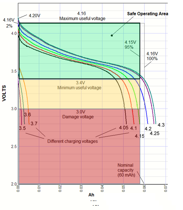
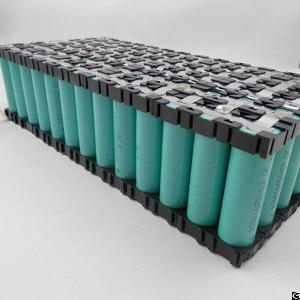
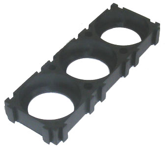
now i've done enough riding to give some feedback about the battery. max voltage is 63V and max current is around 60A (~3.5kW peak). so 6A per cell. sag is more than with the old lipo cell - that was expected, but it's not bad at all. the total internal resistance calculated by my CA is 35mOhm.
range is 50km as calculated with a mileage of around 30Wh/km when ridden hard.
 
999zip999 said:
That's good. Now we need to know cycle life and balance over time. So you have some more work to do. Get to work. Cycle Life.

i can get full 30Ah out of the pack if i charge to 4.20V and discharge to 2.80V. not that i do it every day, but for range tests i did that. i plan to charge to 4.10V.
i don't ride the bike that much that i will get near cell life.
at least balance is excellent. these are screenshots from fully charged and almost empty:
https://www.endless-sphere.com/forums/viewtopic.php?f=14&t=88676&start=575#p1397664
it really need no balancing at all. charging to 4.1V give almost the same results (4.15V is where i start to balance).
 
izeman said:
999zip999 said:
That's good. Now we need to know cycle life and balance over time. So you have some more work to do. Get to work. Cycle Life.

i can get full 30Ah out of the pack if i charge to 4.20V and discharge to 2.80V. not that i do it every day, but for range tests i did that. i plan to charge to 4.10V.
i don't ride the bike that much that i will get near cell life.
at least balance is excellent. these are screenshots from fully charged and almost empty:
https://endless-sphere.com/forums/viewtopic.php?f=14&t=88676&start=575#p1397664
it really need no balancing at all. charging to 4.1V give almost the same results (4.15V is where i start to balance).

I found a "dangerous" site from which I obtained data which you can be interested on:
w w w .powerstream.com/lithium-phosphate-charge-voltage.htm
(not directly linked because it abuses lithium cells)

The data I got:
https://jumpjack.wordpress.com/2018/07/28/tensioni-di-massima-e-minima-carica-batterie-al-litio/

For your specific NCM application:
scarica-lipo1.png


Various curves are the result of charging at different end voltages; please note abuse up to 4.3V!
Cell is 0.060 Ah, which is (probably) fully reached by charging at 4.16 as required.
But chart also shows an unusual data: charging at very low voltage.
Chargin at 3.5V results in almost no energy put into the cell; hence we can assume that 3.4V is the lowest useful voltage for a Cobalt-based cell; any voltage below this threshold is overstressing the cell, as we can see looking at how steep the curves become.
And from 3.4V to 2.8V you can pick just 5% of the energy (0.057Ah vs 0.060Ah).

So I assume that 3.4V-4.16V is the Safe Operating Area of a cobalt cell; 3.0-3.4 range should be reached only upon applying a load; voltage below 3.0 is very deprecated because it causes useless+dangerous stress to the cell.
 
i know some of those tests done, and the result they came to.
i personally trust my own observations and tests and the original samsung' data sheet https://www.nkon.nl/sk/k/30q.pdf
those cells are LiNiCoAlO2 chemistry, and have a LVC of 2.5V. so i don't think you can speak of "cell damage" between 2.8V and 3.0V.
my BMS cuts off at 2.8V under load as "last line of safety", and i did some "real life" measurement, because, like you, i thought that there was no energy left inside the battery below 3V. (you speak of 3.4V). if you stop discharging at 3.4V you are missing 30% of the capacity. even at 3.1V there is still 12% left.
edit: re-read your post. you are talking about under-load-voltage of 3.4V. well. still way too high.
if you discharge to 2.8V, the cells come back to 3.0V after about 10-15min.
 
Indeed the INR18650-30Q charts looks very different fromt that on the site I found.
Which means that each lithium cell management system must be calibrated for each specific cell variant.
According to charts, discharging the cell on the site I found down to 2,5V would be like discharging an INR18650-30Q cell down to less than 1.5V.

It would be interesting to perform on INR18650-30Q the "undervoltage charging test" to see which is the minimum voltage which actually puts some energy in the cell: 3,5V is the value for the cell I studied; maybe for INR18650-30Q it would be 2,5V.
 
jumpjack said:
This is a "battery":
pacco-batteria-litio.jpg


The difference is made by these:
cell-holder-litio.jpg

As far as i know those stackable cell holder are rarely used on DIY e-bike batteries because they are quite expensive, take up more space and you cannot weld large nickel sheets for series and parallel connection at once as you can with the honeycomb design.
In terms of stability or flex i usually glue a honeycomb battery together with Sikaflex or other PU adhesives, and using GFK plates on the sides. It holds up well.
IMO the battery from izeman is build very well and there is no need for a "warning" :)

jumpjack said:
Indeed the INR18650-30Q charts looks very different fromt that on the site I found.
Which means that each lithium cell management system must be calibrated for each specific cell variant.

Thats how it is. Different type of cells have a different 100% DoD voltage.
Usually the "high power cells" should not be discharged to a voltage as low as "high capacity cells" can be. As for instance while a 30Q maybe has 5% capacity left at 3.2V, a Sanyo GA or 35E still have 15% or more left capacity at this voltage.
 
izeman said:
so it goes on. i made the mains connection. a 10mm wide 0.15 nickle strip.
first i cut of 5cm of insulation of the awg12 silicone wire and divided the wires in two parts, twisted those and tinned them.
then i pre-tinned the nickle and soldered the wire to it, pressing it down with a screwdriver bit by bit.


2018-02-01 at 18.10.35.JPG


2018-02-01 at 18.12.32.JPG


safety first. it's really important to isolate wires under voltage.


2018-02-01 at 18.13.08.JPG


pre-tinned the battery tabs as well. with a good soldering iron and 400°C this takes less than a second. so not much heat transferred into the battery.


2018-02-01 at 18.44.34.JPG


welded the strip to the battery. i don't know why, but there were some sparks flying and burnt holes in the nickle. so it doesn't look that nice, and i had to weld at some more points to have 6 valid welding dots.


2018-02-01 at 18.40.48.JPG


2018-02-01 at 18.40.54.JPG


all done, ready to test :) those are not the final wires. just for testing, to see if the BMS is working - which it does! all cells are within 7mV. not what i expected, but good enough. i thought that 5 parallel cells would level each other out closer than that.


2018-02-01 at 18.47.39.JPG

I like the way you put the wire through the whole plate. This ensures the even current path along every cell. I'll use this technique in my next battery pack
 
Back
Top