New Crystalyte 5403 Review by Doc

John, I am planning on making a review. But from now it’s time that is missing me.. the motor is still opened ready for the mods but yes I could modify the name of the thread.

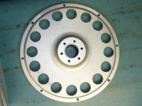
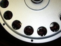
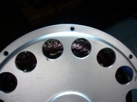
For the 113kmh, I can say 100% sure it was temperature stabilized because while riding I saw the temp rising from 95 celsius and than staying at constant 121 celsius for about 2km at WOT power was 11kW and at that speed the motor efficiency is 80% so 2.2kW of heat to evacuate with a drilled side cover and airflow at 113km/h.

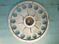
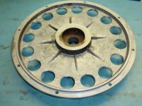
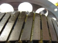
That’s a great observation about the stator angled tooth that improve cooling I never thought about that fact.
I’ll see what can I do with that.

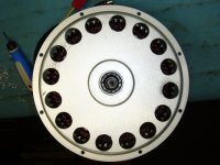
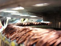
Next for me is to remove the axel and machin it for having wider slot for the 10 gauge phase wire width


For sure i'll make a video of that!
Doc
 
Update: Drilled Side cover!!

I made 16 holes carefully positionnned so that the rehenforced structure part of the center of the side cover is not affected.

The idea is to have the max drilled surface area directly in front of the stator winding to minimize the side cover to reflect the heat produced by the winding and alo to allow more air to circulate.

All holes are 1 inch diameter and are right aligned on the winding :wink:

These side cover are 1/4 inch thick! :shock:

I think i removed 103 cubic centimeter of aluminum ! = 278g total

Well this is the first step for the cooling mod.

Next is to find a hydraulic press to remove the axel to be able to machin it to be able to cary the 3 gauge 10 phase wires.

Doc
 

Attachments

  • P1080808_800x600.jpg
    P1080808_800x600.jpg
    75 KB · Views: 2,439
  • P1080810_800x600.jpg
    P1080810_800x600.jpg
    83.2 KB · Views: 2,439
  • P1080811_800x600.jpg
    P1080811_800x600.jpg
    90.1 KB · Views: 2,439
  • P1080812_800x600.jpg
    P1080812_800x600.jpg
    73 KB · Views: 2,439
  • P1080814_800x600.jpg
    P1080814_800x600.jpg
    91.9 KB · Views: 2,439
  • P1080816_800x600.jpg
    P1080816_800x600.jpg
    65.7 KB · Views: 2,439
  • P1080819_800x600.jpg
    P1080819_800x600.jpg
    71.1 KB · Views: 2,439
  • P1080820_800x600.jpg
    P1080820_800x600.jpg
    64 KB · Views: 2,439
wojtek said:
what is the hub spoke hole size please?

hub spoke hole size : 211-212 mil :wink:
 
Doctorbass said:
These side cover are 1/4 inch thick! :shock:
Wow! I was about to comment about the holes being so large and close together but I guess with a cover that thick you can get away with it.
This thing should take a bazillion amps with those cooling holes 8)
 
Doctorbass said:
wojtek said:
what is the hub spoke hole size please?

hub spoke hole size : 211-212 mil :wink:

My spoke holes are 3.57mm diameter. What am I missing here?
 
itchynackers said:
Doctorbass said:
wojtek said:
what is the hub spoke hole size please?

hub spoke hole size : 211-212 mil :wink:

My spoke holes are 3.57mm diameter. What am I missing here?


a mil is a thousandh of an inch :wink:

a mm is a thousandh of a meter :wink:

It's 39.37mil per milimeter

so in milimeter it's 5.37mm :wink:

Doc
 
LOL... haven't even ran the motor stock yet, or got it spoked.. and you already got holes in the covers.

I love this forum.
 
:D

thanks a lot gentlemen!

3.57mm diameter vs 5.37mm .. hmm i would expect all of 54xx having the same size?


Doctorbass said:
itchynackers said:
Doctorbass said:
hub spoke hole size : 211-212 mil :wink:

My spoke holes are 3.57mm diameter. What am I missing here?


a mil is a thousandh of an inch :wink:

a mm is a thousandh of a meter :wink:

It's 39.37mil per milimeter

so in milimeter it's 5.37mm :wink:

Doc
 
Doctorbass said:
wojtek said:
what is the hub spoke hole size please?

hub spoke hole size : 211-212 mil :wink:

I guess I'm used to you posting in metric. Anyway, I guess I got the small spoke hole version. :wink:

Anyone know how many parsecs it is from spoke hole to spoke hole? :wink:
 
Cromotor Vs 5403 drag race.... :mrgreen:


Seriously, this whole hubmotor thing... where will it end :twisted:
 
WONDERFUL!!!!
Beautiful motor DOC, i'm really curious to see the difference with Cromotor, in performance! :)
I remember my 5404 and this is a great motor, only a bit heavy, but POWERFUL, this 5403 i think is VERY fast!
:)
 
itchynackers said:
Doctorbass said:
wojtek said:
what is the hub spoke hole size please?

hub spoke hole size : 211-212 mil :wink:

I guess I'm used to you posting in metric. Anyway, I guess I got the small spoke hole version. :wink:

Anyone know how many parsecs it is from spoke hole to spoke hole? :wink:

For your pleasure: :lol:
5.37 millimeter = 1.740298479e-19 parsec
 
Ah Doc, you got out of bed at last! :lol:

Now please lace that motor up, get it on a bike and test. pleaseeeeeee :mrgreen:

no more motor pics and data bla bla hurry up man! :twisted:
 
guys, its not going to "go faster" then the 5303... the advantage will be seen when doc goes to a higher voltage AND amperage because it will last longer at those levels, but it's mostly thermal sinking that this extra motor width offers. It will give someone like doc an advantage since he was pushing that barrier before and can now push it harder, but at most it will survive and perform extreme amperage accel better because of a higher saturation point. Anyway, I'm just saying, i want a vid of it on the bike too, but jut watch docs old vids and pretend it's a thicker stator; it will be exactly the same to see everything but the temp sensors, which is just data anyway! The cool thing would be seeing how long it could MAINTAIN say 120km/h. I can put 95km/h WOT (10kw controller) through my current 5304 for my entire battery pack, but it heats up a lot more under hard accel/deccel, enough that at higher energy levels (120km/h prbly 20kw) it might burn up using a 1.5kw hour pack. Going to a 5403 wind and a higher voltage will get me the extra speed I want, and this thicker heavier motor is for lasting through that instead of burning. But just chucking it on my current bike would literally decrease performance due to the extra weight, and gain me only heat sink and maybe some acceleration if I changed my controller; as it is putting out 10kw would remain 10kw in the new motor.
Im actually most interested to see how disk brake callipers will be to fit on there. For some reason the dimensions look tight to me :).
 
Andje said:
...Im actually most interested to see how disk brake callipers will be to fit on there. For some reason the dimensions look tight to me :).
I, too, am very interested in what kind of clearance difficulties we will be running into... especially on the disk brake side.
 
doc why you wanna put 10g phases if 2.74mm is already over 10g, 2.588mm = 10g
 
scriewy said:
doc why you wanna put 10g phases if 2.74mm is already over 10g, 2.588mm = 10g


It's because the existing wire are 11 gauge, not 10... also, the high resistant silicone skin of the wire is better than the existing fragile teflon wire :wink:

I never had any problem with the silicone wire used on phase wie.. but the teflon frafile thin skin can puncture easy and make short... or at high temp it become soft and even more fragile.

Doc
 
Doctorbass said:
scriewy said:
doc why you wanna put 10g phases if 2.74mm is already over 10g, 2.588mm = 10g


It's because the existing wire are 11 gauge, not 10... also, the high resistant silicone skin of the wire is better than the existing fragile teflon wire :wink:

I never had any problem with the silicone wire used on phase wie.. but the teflon frafile thin skin can puncture easy and make short... or at high temp it become soft and even more fragile.

Doc

Doc I very unlikely that you ll have trouble with teflon wires before roasting your winding.
I personally test all my wires in a 180c direct fire and they all survive, being silicon or teflon. I also find teflon coating weak, but the silicon is just as bad under pressure it just looks thick.
 
gensem said:
Doctorbass said:
scriewy said:
doc why you wanna put 10g phases if 2.74mm is already over 10g, 2.588mm = 10g


It's because the existing wire are 11 gauge, not 10... also, the high resistant silicone skin of the wire is better than the existing fragile teflon wire :wink:

I never had any problem with the silicone wire used on phase wie.. but the teflon frafile thin skin can puncture easy and make short... or at high temp it become soft and even more fragile.

Doc

Doc I very unlikely that you ll have trouble with teflon wires before roasting your winding.
I personally test all my wires in a 180c direct fire and they all survive, being silicon or teflon. I also find teflon coating weak, but the silicon is just as bad under pressure it just looks thick.


I guess we probably had differents experience with these two kind of wires, but what i'm sure is that it's a good move. The silicone can be twisted have torsion, etc so when it exit from the axel, it's way less sensitive from puncture or skin damage!

I already had too many problem with the teflon wire. the tefon endout to crack easy after it had high temp. It become less flexible.

180 celsius is nothing fompare to the 260 celsius my 5303 had last summer!.. the guy that used my ebike came back from his ride and the motor was smoking alot!.. when i saw the stator temp on the bbq thermometer i saw 260 celsius and it was decreasing.. assuming that before i saw it, it could have been higher temp! :shock: ...

but guess what... it still work fine today!.. same inductance, same DC resistance, same fun!

the silicon wire are ok.. :wink:

the teflon wire melt curiously at 260celsius... and the silicon are rated 200 celsius.. but from my own experience the turnigy silicon wire solved all my problem since i use them.

Doc
 
Doc you are an inspiration to us all!!

These CRYSTALYTE hub motors are alot of fun, until the axle breaks because water gets into the bearing, the bearing siezes and starts to spin on the shaft, until the shaft breaks at the wire exit landing, due to the excessive stress at at that point. /arrrrrggggg all because of the fact that when you get the motor , you have to do a bunch of modifications, which makes it impossible for water not to get into the bearing area. if you want your wires not to get chewed up, if you want to run hall sensors etc. blah blah blah kenny , max , rewire china, crap, shitty, three hundred bux a year or more to keep bike running just on motors, swapping rear wheels, respoking old motors, nine c cover plates all broken what to do !!!!

WHAT CANT THEY BUILD A GOOD HUB MOTOR, THE AXLE IS GARBAGE and so the rest of the design at the wire exit . Your motor axle just looks rediculous to me, how can it even support itself never mind the bike and you!! i wouldnt trust that thing clamped in a vice on the bench!!!!

sorry Doc :)- i like your torque plates design, have you thought of doing a pinch type design? :D because ultimately i think it was tension on the nut that killed my axle, too much is needed to prevent shaft from rocking in the dropouts with heavy forward/ regen due to slightly rounded dropouts , everyone knows the story
 
file.php


here is the pic, axle looks kinda "pencil like"
 
Yeah.. the axel "look small" :lol: but it work. :wink:

If you use two good torque plate you will never get the axel to break.

The two nut are only to hold the motor in place not to squeeze the axel to avoid it from moving.

what should make the axel from not spining are the two parallel side in the torque plate, nothing else.

myve it can happen that the bearing seize but it ever happened to me on all 5 crystalyte hub motor i had.

I keep the motor hot enough so the water rarely stay in the liquid state!.. it vaporize and exit in the cooling holes :mrgreen:

Doc
 
Yeah good one :) :) will you use any kind of boeing spray like ebike.ca uses now? corrosionx like the big boys use? or mabye impregnate the windings with the epoxy under vacuum. u know what canadian salt will do all those china parts in short order ;)
 
who is this man?
hydro one, go bash another motor somewhere else?
 
Back
Top