New enthusiast with some questions on getting a first bike.

Tell me more about the dropouts on your Mongoose. How wide are they, and what are they made of? Steel, or aluminum?

If they're thick steel, make sure to tighten the nut on the axle as tight as you can, and add either loc-tite or double nut it, or both. You don't want that coming loose.

If they're aluminum (or thin steel), you'll need to investigate a torque arm. That's because the aluminum will fatigue under the torque of the axle, and with these high-power setups, eventually it will fail. This will happen faster if the nuts on the axle aren't tight, so take the above precautions too. The axle can come loose, and then bad things can happen.

A little over a week ago it happened to me, at 10mph on a sidewalk. Hit a pothole, the drops finally gave way, the axle spun inside the drop, two motor phase wires were cut and then shorted. The short fried my controller beyond any repair. At the moment I'm waiting for a new one while using my leg motors instead of my hub motor.

Either way, torque arms are really a topic for another thread. Usually they're custom made because the dropouts different for each bike. (Poweridestore sells torque arms for front wheels, but they won't work on a rear).
 
I checked that out on my bike earlier today. Funny you ask. They are made of steel. Most of the frame of the bike is aluminum, but the rear dropouts are 1/4 inch thick steel. Magnet tested them earlier today. And there is about 6 inches between the rear dropouts. I was also looking at the kickstand on the Mongoose, and I think it can be modified slightly to be a a torque arm/kickstand if I needed one. If not, I can get a torque arm, or make one somehow.
 
Be carefull when making the torque arm. As I learned, the axle tries to rotate backwards..

http://www.endless-sphere.com/forums/viewtopic.php?f=2&t=2261&p=30518&hilit=torque#p30518

DK
 
Ok, so I've been doing some research on the Milwaukee battery packs used by other users in these forums, and I think I'm going to go this route....

http://endless-sphere.com/forums/viewtopic.php?f=3&t=233&st=0&sk=t&sd=a&start=15

I can get the connectors for $7.95 each, and that way I don't have to crack the batteries open, voiding the 5 year warranty.

What do you think?

Update: Well, I went ahead and ordered the Connector Block Assemblies from: http://www.milwaukeeconnect.com/web...-56-1729&p2=&p3=&p4=&p5=&p6=&p7=&p8=&p9=&p10=

Got six of them. I'm going to post in the forum and see if I can find out how JohnDo wired them all together.
 
The problem there is that you cannot run more than two in series, limiting you to 56v. If you go that route and place more than two in series, they'll blow the BMS. Maytag learned that the hard way, here: http://endless-sphere.com/forums/viewtopic.php?t=541&postdays=0&postorder=asc&start=183

The point of running higher voltage, of course, is more power. At the higher voltage, the motor will rotate at a higher speed. It will be able to draw more amps, and thus have more torque. And each amp will carry more energy at the higher voltage. Look at the numbers in the hub motor simulator (ebikes.ca/simulator), and compare the curves of 56v and 84v in a 5304, with all the other correct numbers. The power you can put to the road doubles.
 
Ah crap. Look as though I'll have to call back and cancel the order. From what I was seeing though on these batteries, there's black gunk covering the BMS, and it has to be removed quite carefully, or does wiring the BMS as you stated, require something else alltogether?

Thank you. :D
 
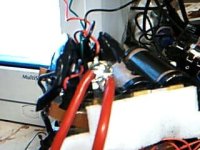
Oh, no, it is covered in black insulating goop, but that's not where you need to solder. Those pictures I promised would help. Basically, there's a wire running from the negative battery tab to the BMS. You want to solder thick high-gauge wire to the battery tab itself, before the BMS. Same for the positive side. Nothing at all is changed in the BMS. You just bypass it.
 
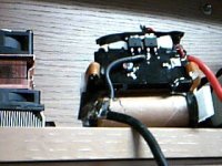
Well, I got out the webcam and took a few low quality shots. Hope they help explain it better.

Picture 5.jpg

Picture 7.jpg

I removed the cases from the packs a while ago, since I needed more room in my bag. What you're looking for is the steel tab to which the thick wires are soldered. You can ignore the second red wire coming off the positive tab; that connects that pack to the other two packs I'm putting in parallel with the pictured one.
 
Thank you so much for the pictures. They definitely help. First off, I don't really understand yet the difference between "Series" and "Parallel" when you guys are talking about connecting your packs together. Ok, so if I want to connect my 6 battery packs in parallel like you're doing, what do I need to do? Do I just do the positive and negative lead on each pack using anderson connectors, and then make a cable that connects them all together, or do I bridge the batteries together, positive to positive, negative to negative? If you removed your batteries from the pack, how are you able to charge them on the chargers?
I have like little kid anxiety going on right now. I still haven't gotten a call from Ebikes.ca on my order. I guess it's only been a day. lol.

I'm also wondering if I really needed to cancel my order for those Connector Block Assemblies. I had an idea for them. Not sure if it would work, but here's the idea.
My idea would be to buy 6 of the Connector Block Assemblies, attach 1 each to the battery packs (6), with the lead off cable coming from the assembly with an Anderson connector on the end for each one. Then, somewhow run a cable from the charging cradles with andersons on the charging end of the cable. That way, I don't have to remove the packs to charge them, I just plug the charger cable into the Assembly's anderson connector coming from the battery. Or would having the assembly always married to the battery cause battery drain?
 
Ebikes.ca sent me the estimate and I paid for it this morning. Everything I need is, or will be enroute. Once I get everything, I will begin my attempt at building my first e-bike. Definitely looking forward to this project. Thank you again for offering your input and any future input that you give.
 
First off, I don't really understand yet the difference between "Series" and "Parallel" when you guys are talking about connecting your packs together.

Okay, this is very important. Every ebike battery is a combination of cells in parallel and series. The configuration determines the volts and amp-hours of a given battery (but not watt-hours) and the number of amps a battery can provide (but not watts).

First off, power is current times potential, so watts=amps*volts. If I have one motor that is drawing 20 amps at 72v and another drawing 40a at 36v, they're both drawing the same amount of power.

In series, you connect one battery's positive to the next's negative, so that when two are added together they have the sum of the voltages. Each Milwaukee V28 battery, for example, contains seven 4v 3ah cells. They're all connected in series (7s for shorthand), and they act as a single 28v 3ah battery. For your setup, the idea is to connect two sets of three of these packs together in series so that they provide 84v 3ah.

7s.JPG

In parallel, you add amps (and amp-hours). If you take two cells and join the positives to each other and the negatives to each other, they'll act as one battery with the same voltage but twice the capacity.

An example of seven cells in parallel:
7p.JPG


So two of those Milwaukee batteries in parallel would provide 28v 6ah (and it would be 2p for shorthand. Since each battery contains 7 cells in series, we'd write that "7s2p", meaning two parallel sets of seven cells in series.) The idea in your setup is to then connect those two sets of three packs in series, each providing 84v3ah, in parallel to provide 84v6ah. (3s2p if you count each Milwaukee pack as a "cell". If you count the individual cells in the packs, it'd be 21s2p).

So, what 21s2p would look like:
21s2p.JPG


Now, no matter how you configure your batteries, you have the same capacity in watt-hours. You need to use watt-hours to compare different capacities of batteries at different voltages because it is the product of the two that determines energy.
 
Thanks for the schooling Laz. I wasn't sure what "7s2p" shorthand meant.
 
Yup, sure thing. Now what have I missed... I need to explain how to charge the things out of their cases?

For simplicity, you can put them back in the cases after bypassing the BMS. Then you can just slide them on the charger like they were stock. I no longer do such because I needed more room in my bag, and the darn cases make them almost twice the size. So, I took the chargers out of their cases and put spade connectors on both, and just charge them that way. I'll add pics later, since I just finished rewiring and packaging them last night.
 
Laz,

Thank you for that, it definitely clears up some of my confusion. Here's what I'm going to do. Once I get the batteries, and figure out how to crack the cases open without breaking them, I will do a mock up of the connection, the takepictures, without actually connecting anything together. I'll post it on here and see if it's right before I actually connect wires and solder.
As for the charger, I'm looking forward to the pics. I am wanting to be able to charge them without having to remove them from the bag each time.

Thank you again for the very useful information. :D
 
...and figure out how to crack the cases open without breaking them

Well, before you crack anything open, charge the batteries. When first placed on a charger, the BMS is activated. Otherwise, the battery will appear dead. It will be partially discharged, somewhere between 75% and 50% charged, from sitting in warehouses. Once the thing is fully charged, then start the disassembly. If you have any problems charging, first try reseating the pack on the charger. If the pack is defective, you need to know about it first, while it's under warranty.

There are five screws that must be removed, with either a torq wrench or a slotted head, either will fit. Then, with a blade, slice the label on the bottom down the middle. The case itself comes in two halves tucked into a top piece. Pry the halves off one at a time. There's a spot where they tuck under the top where they're glued. Just pry it off despite that, and it'll shear clean. The case pieces are very strong; the worst you can do is bend that glue part a little, which can be bent back.

Don't worry about hurting things when removing them from their cases. After the batteries are out, you need to be careful. On either side of the BMS there is a ribbon cable that runs to each cell to balance them while charging. They are easily torn, and a pain in the rear to repair. Also, be careful of shorts. Don't wear any rings or other metal on your hands, either, else it could arc to that and mean bad news for any fingers you may be font of.
 
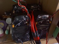
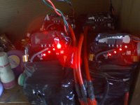
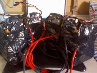
Okay, I got my bluetooth set up, so I can use my 2MP cameraphone instead of the silly webcam. So, my completed batteries:

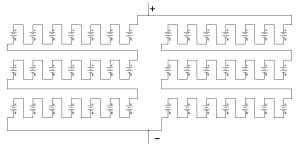
They're arranged in four subpacks, each containing the cells of 3 pack in parallel, forming a 28v9ah unit. The subpacks are then wired in series for a total of 112v 9ah.

0413081811.jpg

The red lights are a state of charge indicator (SoC), a crude fuel gauge. An inoperative SoC points to BMS trouble.

0413081812.jpg

Each subpack uses one 7-cell Milwaukee BMS, with three cells in parallel per "channel". The BMS sees 7 cells, but it is in actuality seeing the average voltage of three cells. The cells will in parallel balance each other, like water seeking its own level.

The diagram is courtesy of maytag. You'd be interested in his emoli build, here: http://endless-sphere.com/forums/viewtopic.php?f=6&t=541

file.php


In this arrangement, one charger fully charges each subpack in a bit under three hours. I use four, one per subpack.

Note the connector block of Andersons at the bottom center. That is where the series wiring actually happens. With the three pairs of Andersons snapped together, I can disconnect just one mechanical connector when I want them isolatrd, like for charging.

Each pack has three wires sticking out of it, which go to the charger. The red is +28v, black is ground, and green is for the thermal sensor. If the batteries are too hot, they will not charge.

0413081817.jpg

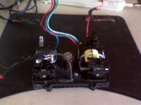
This is the naked charger. I removed it from the case, cutting the plastic around the base with a soldering iron to leave nothing but the charger. The three wires on the outer edges, positive, negative, and thermal sensor, have spade connectors to plug into the batteries. The three in the center go to the intact status LEDs. In the upper left of the charger are two male spades for AC power.

0413081819.jpg

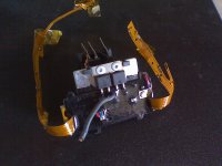
And this is the bare BMS. Note the flimsy ribbon cables. Be careful, as they tear easily.

0413081821.jpg

I also put Andersons on a power strip, so that I have an easy way to power accessories. If you have enough voltage, you can drive AC/DC power suppplies labelled as 'switching adapter', like a cell phone charger or laptop power brick.

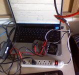
As I write this, I'm discharging them using my laptop so I can test my chargers.

0413081814.jpg

Hope this helps.
 
Laz,

Thank you once again for the detailed information. I hope that I will be able to do this once all of my parts arrive. I'm feeling a bit overwhelmed at the moment on the technical aspect of getting these batteries arranged properly. But as I said, I will definitely be asking for help on this as I start to put things together. I have a great camera, and I will upload pictures as I'm building, both to show what I've done, and ask for guidance on what I need to do. Once I get my stuff, and start digging in, I'm sure it will be easier to develop a plan of attack on this.

Just waiting for my parts right now. Almost everything is still en route. I got the chargers last week, 3 of them, everthing else is still incoming.

Thank you again. :D
 
Ack. I forgot to order something. Do I need the E-brakes for the Clyte motor? My bike has a front Disc Brake and normal rear brake. Will that be sufficient, or do I need to get the E-brakes that work with the Clyte hubs? I'm not even sure what to get. I just heard they make them.
 
Got my batteries today. Charged up the first three and they all tested at 28v after charging on the meter I got. Charging the other three right now. Fingers crossed. Waiting on my new soldering station....

http://cgi.ebay.com/ws/eBayISAPI.dl...ME:B:EOIBSA:MT:11&viewitem=&item=130213312794

....before I start on the battery portion of the project. Ebikes.ca confirmed shipment of the rest of my stuff yesterday, so now just waiting on the Controller, Hub/wheel/freewheel assembly, throttle, and Cycle Analyst.

All batteries are a go. Just waiting on my soldering station, and the rest of everything from Ebikes.ca. Those guys are awesome by the way.They attached the 5-speed freewheel to the hubmotor/wheel for me. One less thing I have to worry about doing now.
 
The 'ebrakes' they sell are nothing more than brake levers with a switch that kills the throttle. The same can be accomplished by... releasing the throttle. They don't actually add braking power.

If you find that you don't have enough braking power, you can always add plug braaking. That's what we call a non-regerative setup where you short the motor windings through a length of wire. Your forward movement will be slowed as power is pulled from the wheel and sent through the wire, which dissipates the current as heat. See http://endless-sphere.com/forums/viewtopic.php?f=2&t=583&start=32 and the following pages for more information.

Of course, any questions are welcome.
 
I'm excited, but it's bittersweet. I received all of the rest of my stuff today to begin assembling my bike. Even got my new soldering station. Had a nice little conversation with the mail lady too aboutthe earthquake we had this morning while I signed for the packages. Everything was fine and dandy, til I realized I am going to be having a house full of obnoxious children this weekend. Dammit...lol. So, I guess I won't be starting until they go home on Sunday morning. I think I can wait that long. Not sure though, it's hard with all the pretty parts sitting right in front of me. I decided to practice my soldering skills and fix my girlfriend's hair straightener. That was a mistake, cause now I'm itching for more. lol. Ah well. I guess I can wait two more days. And man, that hub is heavy. Wasn't expecting it to be that heavy. I'm hoping nothing is damaged. The box I received was pretty well beaten up when it got here. The styrofoam inside was all torn up and all over the place. The wheel was loose in the box because of it. Anywho, I'm going to start by working on the battery setup first. I'll take pictures once I'm ready to begin on Sunday. Perhaps my documenting it will help others down the road.
Oh, and if you want a good and cheap soldering station, get one of those that I linked earlier up in this thread. Holy cow. I think I got it for $83 after shipping and tax, and it's very very nice. It heats to the temp you set it at in less than 20 seconds, it comes with a bunch of replacement tips, like 4 or 5, a spool of solder, and a solder suction pen. It's built really well. I think it's actually better than the Weller's we used when I was doing PCB boards back in the day.
 
Don't worry, nothing can really be damages in shipping in this case. The only thing I'd wonder about is the rim. You'll want to make sure it is true, and shipping can't have been good for that.
 
ARGH!!! The rim is not straight. Does that mean I'm screwed, or can my local bike shop fix it?
 
That's no problem. Any bike shop can true up the rim in no time flat. You can even do it yourself if you have a spoke wrench. Cheap ones can be had for a few dollars.
 
Oh sweet. I thought I was going to end up having to send it back to Ebikes.ca. Thank God it's as easy as taking it to the bike shop on Monday. Hopefully they won't charge me an arm and a leg to do it.

Also, in my time in putting that wheel on the bike, I found that the dropouts are a bit tight for the axle coming out of the hub motor. The dropouts are steel, so could I get away with using my dremel to shave down a bit of the inside of the dropout so the axle fits better, or should I just rubber mallot it in til it won't go any further? Also, the kickstand that comes with the Mongoose bike I'm using, it can double as a rear torque arm. I was excited about that. The hole needs to be filed just a wee bit, but it will be a fully enclosed brace on the axle against the frame. I'll take pics.
 
Back
Top