New enthusiast with some questions on getting a first bike.

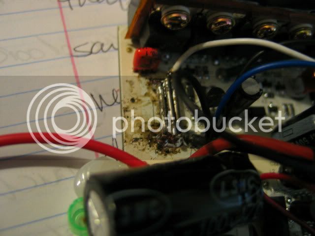
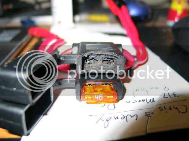
Oh God, I'm freaking out. I got my wheel back today, and I got everything hooked up on the bike. Got the Throttle, Cycle Analyst, and motor plugged into the Controller. The controller was turned off. I hooked my batteries together, 1st set, positive to negative, positive to negative. 2nd set, positive to negative, positive to negative, then hooked both sets together, positive to positive, negative to negative. Then, I hooked the fuse to the battery's positive and negative andersons. Ok, I got all excited, ready to test ride my new e-bike. I plug the cable to the controller into the fuse cable coming from the batteries, making sure positive and negative were lined up. First, a spark, then a sizzling sound, then smoke coming out of the battery bag. I quickly disconnected the battery from the controller cable. The negative line fuse blew and melted completely. What's worse, is it fried one of the BMSs on one of the packs. HOW?!?! ISn't that what a fuse is suppose protect against. All of my other packs are fine, but if Put this one pack on the charger now, the red/green light strobes on the charger. That means the BMS is bad right? I'm scared to death to do anything else. What did I do wrong?! I soldered the battery cables on the batteries like I was suppose to. Now I need to buy another fuse setup and possibly another battery. I can't afford to keep putting money into this. :(
What do I do? I'm freaking out.

IMG_2975.jpg
 
First, get a multimeter and measure the voltage coming out of the battery that was damaged. It shouldn't read anything across the pins that connect to the charger if the BMS is dead. Does the SoC (fuel gauge) light up? And test the battery voltage at the wires you soldered. 99.5% chance that those are normal and the important bits, the cells, are all fine. :)

If you have voltage across the charging pins, try charging it again. Sometimes the BMSs are finnickey.

Also, you want both fuse holders in parallel on only one of the battery wires (doesn't matter which). Put two smaller fuses in, like 25a or 30a, and the fuses will blow when the sum of the rating of the two fuses is exceeded for second or two. As you have it now, you're using a 40a fuse with a 50a controller. If they're good fuses, you'll regularly blow them, which would be bad.

Draw us a diagram of exactly how things are wired. Exactly. And make sure again that you didn't mess up the polarity at any point.

When the failure happened, what was warm? Obviously the fuse blew. Any wires, connections, or batteries warm? And was the smoke just from the fuse and holder?
 
Just a wild guess, but the current surge from plugging in the controller may have tripped the BMS on one pack, causing full voltage to appear across it, blowing the BMS.

This is where those diodes across each battery might come in handy?
Note, the diode trick works with any number of batteries in series, not just two.

 
Mmm, didn't know about that trick. Useful. Anyway, more thinking aloud.

Though, what happened to the BMS is my question. If you did it correctly, and it sounded like you did, the BMS should have been correctly bypassed. It shouldn't have tripped the BMS when no amps were going through the BMS. If it did just trip the BMS, it'll be annoying. Sometimes they get stuck tripped and are useless. Sometimes they fix themselves. If the BMS is blown, though, it gets a little more annoying. Your cells will be fine, and that's the important part. You can still charge them by doubling up on a charger, but eventually you'll need a way to balance the cells.

I'm thinking that if the BMS isn't actually blown, and instead just a little finnikey, it could have just been a bad fuse. The surge from the caps charging would have blown it... but I don't see how that could melt the inside of the fuse holder.

Now, mlrosier, whenever you connect the batts to the controller, a spark is normal. This is a surge of current caused by the capacitors charging. So, a pop is normal. A sizzle is not. A sizzle means a significant measure of current is flowing through something not meant to carry such a current. If everything is connected correctly, the controller (when the throttle is at rest) will only draw a tiny fraction of an amp (other than for the instant when you connect the controller to the batteries). It doesn't matter if the controller is turned on or off then you connect it to the batteries.

Do the clyte v2 controllers have any sort of reverse polarity protection? The old Zener trick, or similar, that would short the battery and blow the fuse if the polarity was reversed?

Again, exactly how were things wired? Check and double-check it, and then tell us. Use a picture/drawing/diagram.
 
Pictures!! My battery that I thought was dead is alive again. It was weird. I did what you said, and tested the plugs on it, they were dead, the positive and negative. The cable I put on it was fine, measured 28v. Then I decided to try and measure the positive and ground on the plugs. They measured a 24v reading. Weird. So then I put it back on the charger. It registered, and charged in like 2 seconds. Then I re-tested the Positive and negative plugs and they registered 28v this time, and now the battery is fine. The Charge state indicator works now too when I press it in on the battery. Here are the pictures for that.

Dead Plugs...
DeadChargerContacts.jpg


24v Ground?
24vPosGround.jpg


Eet's ALIVE!!
28vnow.jpg


Ok, so here is my setup on the batteries, and when they are all connected fully, they register 86 Volts.

First Series...
SeriesOne.jpg


Second Series...
SeriesTwo.jpg


Connected in Parallel Postive...
ParaPositive.jpg


Connected in Parallel Negative...
ParaNegative.jpg


Parallel Positive and Parallel Negative leadout to Controller. Each lead is soldered in line with the battery's protruding cable, and then taped off with E-Tape...
LeadoutParaPosParaNegToCont.jpg


Ok, now for the non-battery stuff. Everything to and from the controller, only connects one way. The Cycle Analyst, the Throttle, the hub motor, they only fit they're matches on the controller, and only fit in one way, and lock in. So I connected them all together. Individually wrapped them with rubber silicone tape, then with electricians tape for added protection. I bundled the Throttle and Cycle Analyst Plugs nearest the controller in Electricians tape and secured them to the frame. The same thing for the Controller and Cycle Analyst connectors at the Hub Motor.

Location of my controller...Bad location?
ControllerLocation.jpg


Hub Motor, Controller Connecter and C/A Connector, indiviually wrapped in Silicone Tape first, then Electricians tape, then bundled together in E-tape and secured to frame...
CAandControllerPower.jpg


Controller, Throttle and C/A Connector, Individually wrapped in Silicone Tape first, then E-Tape, then bundled together in E-tape and secured to frame...
ThrottleandCA.jpg


Battery cable from Controller...
BatteryCablefromController.jpg


And now....for what I didn't notice the first time, which would have saved me all of this headache to begin with....
MyFaultforNotNoticingThis.jpg


And...
BADBADBAD.jpg


Powerwerx bundled the fuse together wrong, and I didn't notice it!!!! I feel like such an idiot!

So basically, I had negative running into positive on the controller, and Positive running into negative on the controller, through the fuses. THANK GOD the FUSE was there. I'm going to email Powerwerx, show them their screw up and ask for a replacement.
 
That is not good at all. I'd check your controller if I were you. That is almost certain death for them, since something usually has to blow for it current to flow through the fuse. I did that once. When I opened the controller, part of the power trace had exploded :shock:.

Amazingly, though. It still worked. I have no idea why, because the reverse polarity should have definitely destroyed the caps, probably destroyed the FETs, and the EMP from the trace exploding should have fried the logic. All it did was break the hall sensor in the throttle.

Also: Why are you using white zip ties? Black ones are much stealthier.
 
How do I check my controller? I don't have any fuses to put inline now. Except for the one 40amp on the Postive line that didn't get fried. Powerwerx is sending me a new fuse assembly free of charge, via 2nd day air, but they want me to send the bad one back to them so they can talk to their staff about the screw-up. I'm thinking I should hang on to the thing until I can verify my controller is ok. If it's fried, I think it's safe to say that they need to buy me a new one. I mean, sure, partially my fault for not noticing the incorrect configuration, but when you order something like that, you expect it to be put together correctly, not having to check it out first. I mean it's Positive/Negative wiring assembly, not rocket science. And they made me feel dumb, and I'm not dumb. I'm angry, very very very angry. Especially if my $275 controller is toast. Please tell me there's a way I can check it out without having to wait until the new fuse assembly comes.

I'm so pissed.

Update: I just sent Powerwerx another email and informed them that if my controller is blown, they will need to reimburse me for a new one. I'm kicking myself for not paying more attention to how they put it together. And kicking at them for not putting more effort into quality control before shipping out a product.

You know what's funny, I think I have a Gremlin messing with me. This kind of stuff has been happening to me ALOT lately. I got a flashlight cap for my flashlight the other day. THey sent me the wrong one and it didn't work. Then yesterday, I got a box in the mail that was suppose to have a cable in it I ordered for a Voice Recorder I have, and instead it was a camera case. Is it possible that Gremlins exist and they like making people miserable?
 
You could pop in a couple of 5A fuses and test for continuity... if yes, you could hookup (properly) and test for operation. The 5A fuses should protect from a short.

Even if one fuse holder is shot, you could short across it and test with 5A in the other.
 
Hey Tyler,
Well, I only have one fuse holder left. It has a 40a fuse in it. I don't have any spare anderson connectors left either. So I don't think I can hook anything up until I get the replacement fuse holder. If I were able to do anything, I think I'd need someone to show me exactly what they mean. At this point, I'm not sure I trust myself anymore to get things right. lol.
 
Link said:
Also: Why are you using white zip ties? Black ones are much stealthier.

I have a gut feeling that my controller box is gone. My luck isn't good enough for it to be otherwise. So when I take everything apart, I'll make sure I buy some black zip ties to replace the white ones. God, if the controller is blown, it's going to suck unhooking everything. I used ALOT of tape. lol. :( I just hope that if it is blown, Powerwerx doesn't try to cop out, and actually works with me on reimbursing me for the controller, otherwise, I'm screwed. I'm out of money, and won't be able to buy a new controller for a few months. :(
 
If it were me, I'd find a pair of 5A fuses in my auto-parts bin and see if they work in the fuse-cable assy., by checking for continuity end-to-end on the pos and neg lines.

If good, I'd connect as planned (properly) and see if the setup works. Powered-up, your motor should turn with application of throttle. If there is a problem, your controller may be toast. The small fuses will protect your packs if there is a short in the controller.

You can also open up the controller case. Usually it will smell burnt, if things went south.
 
Sorry Tyler. I feel like such a noob right now. lol. I don't know what you mean by checking for continuity end to end on the positive and negative.
Do you mean take the good fuseholder and 40a fuse and run it to Positive on the batteries and positive on the controller, and then just make a Negative to negative anderson cable to go from negative on batteries to negative on Controller with no fuse in line? One of the fuse holders is fine. The other one is melted, but the wires and anderson connectors are fine. Ah crap. I can tear the thing apart. Powerwerx wants me to send it back to them. Nevermind
 
mlrosier said:
Sorry Tyler. I feel like such a noob right now. lol. I don't know what you mean by checking for continuity end to end on the positive and negative.
Do you mean take the good fuseholder and 40a fuse and run it to Positive on the batteries and positive on the controller, and then just make a Negative to negative anderson cable to go from negative on batteries to negative on Controller with no fuse in line? One of the fuse holders is fine. The other one is melted, but the wires and anderson connectors are fine. Ah crap. I can tear the thing apart. Powerwerx wants me to send it back to them. Nevermind
Yep, you got the idea.

Checking continuity is simply using your meter to see if there is a complete connection through the fuse wires, with the fuses in place.

You really only need one fuse in the pair, since they are the same circuit. A small fuse rating is better for testing, so if there is some kind of problem, you won't damage more stuff.

(It looked like the melted fuseholder could still accept a fuse, but I could be mistaken. )

FWIW, It's not a major disaster, but a significant inconvenience. You didn't get hit by a car on the first ride or set your house on fire. Damned frustrating, to be sure.

:?
 
Glad to see things worked out with that BMS. That's good news.

For future reference, that middle pin is for the thermal sensor to the charger, and other problems. It'll be at ~5bv above ground, depending on things. The one on the far right is the real ground.

Also, this will cause you problems:
CAandControllerPower.jpg


If you get a flat on the road, this will make a bad day worse. You need to be able to remove the wheel, so don't use zip ties on the motor cables before they connect to the controller, and you don't need to use so much electrical tape. :shock:

You don't even need zip ties for the wires; you can just use electrical tape for a stealthier look. I mean, you just need to hold them to the frame, not support any weight.

Checking continuity is simply using your meter to see if there is a complete connection through the fuse wires, with the fuses in place.

Your meter will have a setting for continuity (should be a binary, yes or no), or resistance (in Ohms), or both. I recommend using the Ohm meter setting. Anything under a few thousand Ohms is a connection. Anything above one Ohm, in a battery line, is a bad connection (it'll heat up and fail. Your battery wiring resistance should be effectively zero, so low that your meter won't get a measurement. If you intermittently get a little resistance, press harder with the probes).

When you take off your controller, shake it. If you hear sand or small things rattling, something is definitely blown. Very bad.

Use your meter to check continuity between the controller's battery wires. Between the positive to battery and negative to battery, you should have no path (effectively infinite resistance). If you have a path, you have a problem in the controller. Very bad.


Again, you don't need fuses in both the positive and negative of the battery circuit. Just one or the other. Fuses in both is unnecessary and introduces extra resistance.
 
lazarus2405 said:
If you get a flat on the road, this will make a bad day worse. You need to be able to remove the wheel, so don't use zip ties on the motor cables before they connect to the controller, and you don't need to use so much electrical tape. :shock:

You don't even need zip ties for the wires; you can just use electrical tape for a stealthier look. I mean, you just need to hold them to the frame, not support any weight.

Gonna have to disagree with you there. Having the motor wires dangling without any support is NOT a good idea. Besides, just carry a few extra ties and small wire cutter with you. They don't take up much more space than a spare tube.

Electrical tape tends to get sticky and nasty down the road.

TylerDurden said:
If it were me, I'd find a pair of 5A fuses in my auto-parts bin and see if they work in the fuse-cable assy., by checking for continuity end-to-end on the pos and neg lines.

He doesn't even need to find a fuse. Just check continuity from the end of the wire to the fuse holder on both sides.

mlrosier said:
How do I check my controller?

Open it up before you try to put any more power into it. Disastrous failures like yours might have been usually have pretty telltail signs. Look for bulging/burned capacitors (big cylindrical things). Check the FETs (there should be a lot of them attached to a heatsink. they have three legs each) for burn marks. Have a look at the power traces. They might be burned/partially exploded.

If everything looks okay, try to get it to run. You MUST have a fuse when you do this. If it does, consider yourself very lucky. Like Tyler and I said, it's very rare to have a controller survive a backwards connection.
 
You guys forgot twist ties. The phase and hall wires comming from the controller I zip tied to the frame, but the phase wires and hall wires from the motor i just twist tie them using some cheap twist ties that came with trash bags. Some small guage wires work too. Just a few turn to hold it in place. I don't want to tighten it down because if the dropout ever fail i want to make sure the twist tie will gives and let the wire go. Don't want the wire being rip out by the zip tie holding it back. As far as fuse, carry a spare one. Tape that onto the side of the fuse holder. That way you have spare if it ever blew up on current spike. I find this out the hard way having to peddle home after a blown fuse.
 
Like Tyler and I said, it's very rare to have a controller survive a backwards connection.

Agreed. It's my understanding that "very rare" in the context of the Crystalyte v1 controllers is better described as "never". No idea about the v2 units.

Open it up before you try to put any more power into it.

Agreed. Post pictures, too. Before you do, though, check for continuity between the battery wires from the controller. Though, I wouldn't hold out much luck. From what you've said, it sounds like there will be, meaning a short inside the controller and thus a blown somethingorother.

You have a v2 controller, so it'll be easy to open up. Remove the four screws at each end and the five on the side, twist the end cover with the power button around so it'll fit in the case, and pull the circuit board out from the other side. Do not pull by any of the small wires like Hall sensor or throttle connectors. They'll rip off the board and you'll have to resolder them.

Once you have the board and the aluminum heatsink block out of the case, look for problems. They will be obvious. The row of things screwed to the chunck of aluminum are the FETs, and they should be examined. If one is blown, you'll know it when you see it. Check the capacitors, too. Again it should be easy to tell. if they are blown. Check traces on the front and back of the board. The board is white, so it'll be very easy to see any telltale burn marks.

If anything looks suspicious, please post pictures. Also, this thread would help: http://endless-sphere.com/forums/viewtopic.php?f=2&t=3896

Let me explain about the electric tape. I used it for small wires, like from the motor to my plug brake, or a 12v to a light, and I didn't wrap around the frame but rather along the wire. It ends up looking more like a stripe than a wire. Dunno how it'll fare with time. I suggested electrical tape because he's obviously got a lot of it, and is easier to remove than zip strips. :D

The real answer is Velcro cable ties. They sell 'em in any home improvement or office store, and they work great. Put them on any wires you might have to remove, and wrap the Velcro around frame tubing and onto itself. Removable, reusable, requires no tools, and tolerates moisture far better than tape would.

I dunno about the twist ties. I'd think they wouldn't tolerate vibration as well as zip strips or Velcro. If they work for you, though, then that's experience versus an uninformed opinion. However, if we used twist ties, I think we'd all end up with stale bread, irate women, and not much to show for it.

Agreed on spare fuses. I keep a small bag with a range of values, in case something happens and I want more current through that fuse or need less, say, if a subpack couldn't be used.
 
Thanks for all of the help guys. I really do appreciate it.I'm going to take everything apart after breakfast so I can check the controller out. Also, would one of you be willing to put up a picture showing this testing for continuity stuff? I am really having a hard time wrapping my head around that, and need to be shown. I have mental dislexia. :( I would be super grateful.

More to come...
 
Ok, so I think I tested the controller for continuity right. I put the multimeter on the "Speaker" icon setting. Also tried it on 2000 OhM. It reads a "1" without doing anything. If I touch the probes together, it shoots up over 1000 then drops to 0 OhM or buzzes, showing continuity. If I put the black probe in negative on the controller battery in terminal and the red probe on Positive, I get no beep, and the digital display stays at "1". I did this with a fuse in line on positive, and without the fuse. Same result, both times, either settings. :(

Second, I took everything apart, and took the controller apart. I'm not sure what to make of it. Bad soldering job, or something got very hot and spattered? Not sure.

The whole board...
WHoleBoard.jpg


Back of the board...
WholeBoardBack.jpg


Good...bad...?
BadSolder_1.jpg


BadSolder_2.jpg


BadSolder_3.jpg


So now, unless I did something wrong, I will be contacting Powerwerx and asking them to reimburse me for my controller, since it's their screw up that did this. I feel sick to my stomach right now. :(
 
Actually, it looks more like a crappy soldering job, when they increased the material in the shunt. Hard to say...

Since the FETs and caps ain't blown to bits, it might actually still work ok.

Use your meter to check just the fuse cable with the fuse installed. If it's OK (zero resistance/ beep) get some 5A fuses and hook the sucker up for a test.

:D
 
The fuse by itself, tests fine, it beeps, but the controller itself is not. Am I doing the continuity test right on the controller? Black probe in negative, and red in positive on the battery cable on the controller? If I am, it's reading a one, not a 0 or a beep. Which means there's no continuity, which means something's broke, right?

And also, since I don't have anymore anderson connectores, I have no way to run a test, because I would only be able to hook up the positive leads from battery pack to controller. :(
As for the fuse, I have a 40amp plugged in, so would that be fine if I don't have any 5amp ones, provided I could find a way to make a bridge for the negative leads from battery pack to controller terminal.

I was wrong, I do have a few andersons left. But I don't want to make the cable for the negative to negative until I know for sure that I'm right or wrong on the controller conintuity test.

Also, if what you see inside, is a result of a bad soldering job, should I take my complaint to Ebikes.ca and ask for a replacement?
 
mlrosier said:
The fuse by itself, tests fine, it beeps, but the controller itself is not. Am I doing the continuity test right on the controller? Black probe in negative, and red in positive on the battery cable on the controller? If I am, it's reading a one, not a 0 or a beep. Which means there's no continuity, which means something's broke, right?

If you're reading a 1, that's good. A 0 would indicate a short, which would be bad. Try reversing the test probes and see if you get a continuity reading for about a second or so.
As the capacitor charges up in the controller, the continuity will disappear, so this is probably normal.

The spatter stuff is messy looking, but by itself does not necessarily indicate a problem.

Next step would be to try and power up the controller with some kind of current limiting. A 5 amp fuse would be good. A car headlight in series works too. You could test with a lower voltage. Anything over 20v or so should be enough for the LED indicator on the controller to work. You want to apply power and see if the LED lights up.
 
Back
Top