Watermelon Wine
1 µW
Hello all!
Paul from Australia here, pretty new to the electric scene but definitely a convert!
So it's a bit of a long story, but background info can be important for understanding intended use...
Maybe 6 or 7 years ago I went to China to catch up with some friends from earlier times. (Shaoguan, Guangdong province)
Whilst there I bought a brushless hub motor (48V 800W) and controller (48V 600W, the only one they had available). (You can see it starting to go off the rails already...)
In the shop they asked 'what size wheel?' ...I knew I wanted torque so kept asking for smaller and smaller, eventually the light struck someone's eyes and they appeared with a scooter motor with a 10" rim welded directly to the 9" magnet ring. When I saw it my eyes lit up too and it was; "Sold!"
When I got home I put it in a 26" soft-tail pushbike with the front wheel still at 26"... It looked terrible but performed better than expected. From there it went into a dead 125cc pitbike frame with 4x 12V 7Ah "alarm batteries" with the little 6mm spade terminals
 Surprisingly, I was still happy with it and used to tootle a few hundred yards back and forth down the street to my friends' places. Range on flat ground would have been about 2 kms.
My wife and I had kids and bought a farm out of town with an average gradient of about 5:1. ...That's when I started doing really terrible things to it like riding straight up the hill with a flat battery until it stopped and the controller stopped giving me power, (all you have to do is let the throttle off to 0% aim 45 degrees off the slope to get started and you're good to go again... :wink: :lol: )
Anyway, I got sick of it, decided I wanted to convert it to a mid-drive to take advantage of the joys of adjustable gearing ratios and put it in the lathe to chop all the unnecessary bits off. Halfway through the conversion I got busy with other things and it gathered dust.
That was a few years ago and I've now learnt a little bit more about electricity via investigations into running an off-grid solar power supply in the shed that's on the farm. (8kW continuous, I can weld with it! )
)
After thinking about how to solve some of the problems I had created for a few years I recently got back into it...
Here's where it's up to:

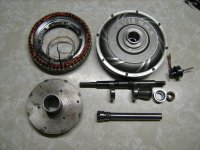
To keep everything strong and straight, but still allow servicing, I ended up buying a 20-19mm (id) collet from an ER32 collet chuck and turned the 8 degree and 30 degree cones required to clamp it onto the shaft.
If I had have had any sense at all I would have bolted a 30 tooth back sprocket onto the side of it, run it to a 50 tooth, and been done with it. Having done it the hard way however, I now have the ability to drive a lot more things with it... The top shaft is from the original motor and will be used for the first testing, but the bottom shaft is a 'precision' ground 20mm straight hollow shaft with an ER20 collet chuck already in the end of it. ($11 on eBay) This, I'm hoping, will let me power all manner of prop shafts for boats/canoes/catamarans/lawnmowers/milling machines/whipper-snippers etc. just by choosing the collet that matches the shaft.
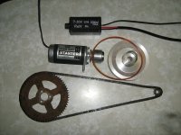
After having had so much time to think things through, I've realised that using any 'normal' sort of motorcycle gearing will leave me travelling slower than walking pace and drawing absolutely zero amps. To combat some of this, (but still keep the torque increase I was hoping for) I've bought an 18T front and 37T rear sprocket. This should let me climb trees, at around walking pace, whilst still drawing nearly zero amps.
This would keep me happy, but 20-30km/hr top speed of arm-stretching torque would just add that little giggle factor. (My last two motorcycles were the GSX1400 and ZX12R, neither of them required much use of the little gear-shifting thingy...)
So! My questions: (Does anyone know the name of this type of motor?!? It is dot matrix printed: "BC48V800W1106085")
I understand kV, (even though I don't know what the kV is for this motor) and would like to make it go around faster! Just how many volts can I send through a motor such as this before I run into limitations? Some of the limitations I can see (through using the search function) might include; the ability of the controller to switch fast enough, spark jump for lack of insulation properties, simply frying it from heat, which I can understand, and many other things that are well above my head to do with efficiency losses through back EMF, eddy currents etc.
What limitations will I crash into first? Is it only amps that causes heat? wattage? some combination of the two? Can increased voltage, (without increasing wattage, thus reduced amps) EVER cause heat?
No doubt I could have saved a lot of work by buying a bigger controller a few years back, at the moment I'm looking at buying something like this: (Wide voltage 48-72V 1500W)
http://www.ebay.com.au/itm/48V-72V-1500W-Electric-Bicycle-E-bike-Scooter-Brushless-DC-Motor-Speed-Controlle-/201744222866?hash=item2ef8e48a92:g:cOkAAOSwnHZYSgT-
There seem to be two types, one with a voltage selector, and one without. Is there a difference? Should I shunt-mod this one? Should I shunt-mod my old one?
Should I cut cooling slots in the rotor bell?
Eventually I can see that I'm going to smoke this motor and re-wind it, and that's okay. I'm even considering building a whole new rotor with stronger magnets, more steel, and smaller air-gap (or whatever you guys recommend! :lol: )
Help me get the smoke out of it.
School me.
Cheers!
Paul.
Paul from Australia here, pretty new to the electric scene but definitely a convert!
So it's a bit of a long story, but background info can be important for understanding intended use...
Maybe 6 or 7 years ago I went to China to catch up with some friends from earlier times. (Shaoguan, Guangdong province)
Whilst there I bought a brushless hub motor (48V 800W) and controller (48V 600W, the only one they had available). (You can see it starting to go off the rails already...)
In the shop they asked 'what size wheel?' ...I knew I wanted torque so kept asking for smaller and smaller, eventually the light struck someone's eyes and they appeared with a scooter motor with a 10" rim welded directly to the 9" magnet ring. When I saw it my eyes lit up too and it was; "Sold!"
When I got home I put it in a 26" soft-tail pushbike with the front wheel still at 26"... It looked terrible but performed better than expected. From there it went into a dead 125cc pitbike frame with 4x 12V 7Ah "alarm batteries" with the little 6mm spade terminals
My wife and I had kids and bought a farm out of town with an average gradient of about 5:1. ...That's when I started doing really terrible things to it like riding straight up the hill with a flat battery until it stopped and the controller stopped giving me power, (all you have to do is let the throttle off to 0% aim 45 degrees off the slope to get started and you're good to go again... :wink: :lol: )
Anyway, I got sick of it, decided I wanted to convert it to a mid-drive to take advantage of the joys of adjustable gearing ratios and put it in the lathe to chop all the unnecessary bits off. Halfway through the conversion I got busy with other things and it gathered dust.
That was a few years ago and I've now learnt a little bit more about electricity via investigations into running an off-grid solar power supply in the shed that's on the farm. (8kW continuous, I can weld with it!
After thinking about how to solve some of the problems I had created for a few years I recently got back into it...
Here's where it's up to:

To keep everything strong and straight, but still allow servicing, I ended up buying a 20-19mm (id) collet from an ER32 collet chuck and turned the 8 degree and 30 degree cones required to clamp it onto the shaft.
If I had have had any sense at all I would have bolted a 30 tooth back sprocket onto the side of it, run it to a 50 tooth, and been done with it. Having done it the hard way however, I now have the ability to drive a lot more things with it... The top shaft is from the original motor and will be used for the first testing, but the bottom shaft is a 'precision' ground 20mm straight hollow shaft with an ER20 collet chuck already in the end of it. ($11 on eBay) This, I'm hoping, will let me power all manner of prop shafts for boats/canoes/catamarans/lawnmowers/milling machines/whipper-snippers etc. just by choosing the collet that matches the shaft.
After having had so much time to think things through, I've realised that using any 'normal' sort of motorcycle gearing will leave me travelling slower than walking pace and drawing absolutely zero amps. To combat some of this, (but still keep the torque increase I was hoping for) I've bought an 18T front and 37T rear sprocket. This should let me climb trees, at around walking pace, whilst still drawing nearly zero amps.
This would keep me happy, but 20-30km/hr top speed of arm-stretching torque would just add that little giggle factor. (My last two motorcycles were the GSX1400 and ZX12R, neither of them required much use of the little gear-shifting thingy...)
So! My questions: (Does anyone know the name of this type of motor?!? It is dot matrix printed: "BC48V800W1106085")
I understand kV, (even though I don't know what the kV is for this motor) and would like to make it go around faster! Just how many volts can I send through a motor such as this before I run into limitations? Some of the limitations I can see (through using the search function) might include; the ability of the controller to switch fast enough, spark jump for lack of insulation properties, simply frying it from heat, which I can understand, and many other things that are well above my head to do with efficiency losses through back EMF, eddy currents etc.
What limitations will I crash into first? Is it only amps that causes heat? wattage? some combination of the two? Can increased voltage, (without increasing wattage, thus reduced amps) EVER cause heat?
No doubt I could have saved a lot of work by buying a bigger controller a few years back, at the moment I'm looking at buying something like this: (Wide voltage 48-72V 1500W)
http://www.ebay.com.au/itm/48V-72V-1500W-Electric-Bicycle-E-bike-Scooter-Brushless-DC-Motor-Speed-Controlle-/201744222866?hash=item2ef8e48a92:g:cOkAAOSwnHZYSgT-
There seem to be two types, one with a voltage selector, and one without. Is there a difference? Should I shunt-mod this one? Should I shunt-mod my old one?
Should I cut cooling slots in the rotor bell?
Eventually I can see that I'm going to smoke this motor and re-wind it, and that's okay. I'm even considering building a whole new rotor with stronger magnets, more steel, and smaller air-gap (or whatever you guys recommend! :lol: )
Help me get the smoke out of it.
School me.
Cheers!
Paul.


