New member taking the plunge with an eBay kit

http://www.hobbyking.co.uk/hobbyking/store/__15521__Turnigy_5000mAh_4S1P_14_8v_20C_hardcase_pack.html

http://www.hobbyking.co.uk/hobbyking/store/__56840__Multistar_High_Capacity_4S_5200mAh_Multi_Rotor_Lipo_Pack.html

http://www.hobbyking.co.uk/hobbyking/store/uh_listCategoriesAndProducts.asp?cwhl=XX&idCategory=86&v=&sortlist=P&LiPoConfig=6&CatSortOrder=asc


http://www.thunderpowerrc.com/Products/Chargers_2/TP1430C

http://www.endless-sphere.com/forums/viewtopic.php?f=14&t=23362

You really want the Celllog 8S that does logging, not the 'M'
http://www.progressiverc.com/celllog-8s.html


As for bulk charging search for PC PSU conversions. So you would get 4 working PC power supplies from scrap PC's and modify 3 of them, then stick them all in series for a free 50volt charger.
Also can use a single one to power the Hyperion balance charger.
 
Samd said:
Whoa - did I see a torque arm at the rear?
That does it! Sick of the lack of safety here, I demand we perm ban BMboomer and firewall his IP so he can never reach this site again!
:twisted:
Nar JKing, not his fault as it doesn't appear to be a torque arm provided in that kit. Also most of those Dunlop bikes are %100 steel frame.
 
Nar JKing, not his fault as it doesn't appear to be a torque arm provided in that kit. Also most of those Dunlop bikes are %100 steel frame.
The Dunlop frame is steel, and it has long dropouts into which the axle flats were a very snug fit. Also the kit, although not coming with torque arms, did have big thick torque washers which fit over the flats of the axle, and have lugs which effectively extend the flats further into the dropouts.
This is my first forray into the world of DIY ebikes, and I'm just using this bike to test things out, and to see if the kit is any good & what sorts of extra things or challenges I'm letting myself in for.
I expect to be fitting it to a better bike later, and if I do, I will get all the bits & pieces that are needed first, including torque arms, so that everything will be on hand.
 
Hi folks
haven't posted any updates about my journey with this kit for a few weeks as I've been ordering stuff on Ebay/HobbyKing, and it takes ages to arrive, so I've just been using it with the Power Tool batteries, and hadn't made much progress.
I contacted the seller about the spokes not being stainless as listed, and they offered me a $20 refund which I took.
I took the comments on board, about an Imax B6 battery charger not being powerful enough, and I shelled out on a new icharger 206B (Ebay about $90), which is great.
I have also bought a new Amacrox 750W PC PSU with 4x 20amp 12v rails (Ebay $51 inc postage), to power it.
I got an amp/voltmeter to use as a battery guage from Ebay, but I find I also need a shunt to use the ampmeter part, so that's ordered, and I'm still waiting on it. I can still use the voltmeter part though, and it works great, and reads the same as my DIMM.
I'm still waiting on 1-8s low cell voltage buzzers, and balance leads.
I got a whole bunch of silicone wire , heatshrink, and HT60 connectors from HobbyKing, and an HT60 series lead, and a parallel one.
I haven't bought any HK lipo yet, as I've got some new laptop batteries from Ebay for about $15 each. I've got 4 of them, but the seller hasn't got any more unfortunately.
The laptop batteries have got 6 Samsung 2600mAh cells in each, arranged as 3s2p. I've checked them with the icharger, and they are all good and take their full capacity.
I can use them just as they come out of the laptop packs, in 3 long, 2 wide sticks (my wife thinks they look like sticks of dynamite). All the balance taps are already there, ready to connect my balance leads to, when they arrive. Also they all fit in the controller bag that came with the Kit.
I have made 2 packs with 2sticks in each, wired in series, so that I have 2x 6s2p packs. I have used the HT60 connectors on them, so that I can use the HT60 parallel lead to make 6s4p for charging, or the Series lead for on the bike, to make 12s2p (44.4v nominal at 5.2Ahrs). That's not much capacity, but its more than 3 times the power tool battery capacity, that I have been using, and 20% more voltage. The continual discharge rating of those cells is a bit low at 2C, but at a full charge, they are giving over 50v , so at 10.4 Amp discharge they would produce over 500W. I tend to use the assist very lightly, so I think they will be fine for me.
Anyway I have put it all together to try it, and have hit a snag that I'm hoping someone can help me with.
Fully charged, all the lights come on on the throttle, and the voltmeter is reading 50.2v, but no go, on the throttle or the PAS.
So after some experimentation, with discharging them, and re-trying them, I find that the controller has a high voltage cut out at 46.2v.
My question is, can I raise that by 4v or so? There are some pictures of the insides of the controller earlier in the thread. Please bear in mind that my knowlege of electronics is pretty basic.
 
Short answer. ... NO.


Long answer...,The answer is very likely yes, it is possible.

But as it appears to not be a board type that no one here recognises, the chances of actually being able to do it (without an electronics expert getting it in his hands) are very slim to non existent I am afraid


Somewhere on the board there is going to be the Master Control Unit (MCU)

There will likely be a voltage monitor line into it,with a pair of resistors acting as a voltage divider bridge. The resistors will act as a scaling device, outputting a low signal level voltage in proportion to the input voltage


It would be a matter of tracing the PCB to create schematic and then some calculations and micro soldering to change some of those SMD resistors.

The other way may have been to see if the row of empty solder points starting with label A3 are actually part of the programming header..... if it exists.

This is the danger of many of the unknown e-bay kits compared to the known ones, where all this work has already been done.
 
By the sound of it, it would probably be beyond me to be able to do that sort of alteration.
That leaves me with a couple of options.

I could buy some more of those Samsung cells and change my configuration to 2 lots of 5s3p & stick to more or less 36v. I'd need to get another 6 cells. The cheap lappy batteries are gone, but I can get the same cells from Fasttech for about Aus $4.50 each.

Or I could get a different controller, Like this one. http://www.bmsbattery.com/controller/552-s06-250w-imitation-torque-square-wave-controller.html
They say this is for 36v or48v systems. How does that work with the different Low voltage cut off requirements? I wonder if all the other bits of the kit would fit it?
Has anyone tried these torque simulation Sine wave controllers? Shipping to Aus would cost more than the controller from BMS Battery.
I had a ride of the bike, using the half charged new 12s battery. It will only work on this controller if I only charge it to lipo storage voltage.
I certainly like the extra go it's got compared to the 10s power tool batteries, although they're not bad when they're fully charged.
The new one has got good go, right to the end.
Other things I noticed, are that the voltmeter is completely unreadable in the sunlight, and also I get quite a lot of voltage sag when its pulling hard.
The specs for those cells give a discharge cut off voltage of 2.75v, but most people recommend not to let 18650 LiIon's go below 3.00v. That would be 36v on my voltmeter.
Thing is that even when I've got 44v at idle, it will dive down to that, when the PAS cuts in, until it gets up to speed. Even a bit lower on hills.
Will that voltage sag damage the batteries?
When using the voltmeter to guage when to call it a day, should I be looking at those dips, or the recovered voltage when it's running light or idle?
I just used the average light running voltage today, as a guage, otherwise I wouldn't have hardly even got a ride out of it.
Doing it that way, I got 14kms out of that half charged battery, with minimal pedal effort. I turned it off when it was averaging about 36-37v at idle.
When I got home the battery was pretty warm. Probably not helped by my attempts to protect it from getting knocked around by wrapping it in thin packing foam and duct tape. Might have to re-think that.
 
that 8 pin SOIC is most probably the voltage regulator but from the bottom i saw there is a three terminal device but none of you front side pictures show it so it is under one of the wires. so that may be the 7812.

do like neil said and find the voltage divider that comes off of the input voltage and carries a trace from the middle over to the mcu. if you find that you can add another resistor to lower the resistor divider output to the mcu. but you indicated it turns off at 44V for LVC which does not make sense.

the reason the battery voltage sags so much and your batteries get hot is because they are not big enuff to carry the load you pull from it.
 
At work now, can't give long answer.

Best option probably controller

Look at Lyen.com

Or E-crazy man / Keywin controllers on e-bay

Both the same controllers 6 FET 4110 would do you.
 
This is keywin (e-crazyman) ..well one of his sold items.

just mail him at ecrazyman@gmail.com via e-bay and he will either create a sale item for you or send you a PP invoice.

http://www.ebay.co.uk/itm/260947486400?ru=http%3A%2F%2Fwww.ebay.co.uk%2Fsch%2Fi.html%3F_from%3DR40%26_sacat%3D0%26_nkw%3D260947486400%26_rdc%3D1

His controllers are pretty much the same as Lyen's . I guess they both use the same supplier, as their controllers look identical. Lyen does repairs as well though..hot sure about Keywin. So if you buy from Lyen, and it goes wrong, you stand more chance of getting repair.

from Ed

http://lyen.com
http://endless-sphere.com/forums/viewtopic.php?f=31&t=18744


Can not comment on the BMS sine wave controllers, never tried a sine wave unit yet. though they are now becoming popular.


Yes, cells get hot if you take too much out of them ..so paralleling them is a good idea...but ideally only if they are from the same batch. That even goes for series wiring too. Yes of course you can series and parallel all sorts of different cells and it will work to a point..but weak cells will go flat early..so the stronger ones 'take over' . If a cell goes dead in series while the others are still at a good voltage..then they dud cell gets pushed in to reverse polarity..or it can..then

All in all , not worth mixing cells.

I'd make up what ever you can for now with just the cells you have, then either build a second pack ..so go out on one pack, home on another.

As for when to gauge the cell voltage...well, resting idle voltage should never go below the minimum, and yes under initial acceleration they can drop for a short period under the 'safe' voltage. Not ideal, but probably not gogin to permanently damage them..from my experience of LiPo...but you are using the 18650's so ???
 
that 8 pin SOIC is most probably the voltage regulator but from the bottom i saw there is a three terminal device but none of you front side pictures show it so it is under one of the wires. so that may be the 7812.

do like neil said and find the voltage divider that comes off of the input voltage and carries a trace from the middle over to the mcu. if you find that you can add another resistor to lower the resistor divider output to the mcu. but you indicated it turns off at 44V for LVC which does not make sense.

Hi again, it doesn't turn off at 44v for LVC, I was just meaning that when I'm going along just idling/light running, and the voltmeter is showing 44v, the voltage can dive down below 36v when the PAS comes in, as when it does, it gives it full power. It doesn't make the LVC cut out. I just don't like seeing that on the voltmeter, because at that point, it's pulling my 12s cells down to below 3v per cell.
I've had a couple more rides, and I can regulate the voltage sag much better just by gentle use of the throttle, and the battery doesn't get so hot that way.
For the PAS to be usefull it really needs to have some levels of assist. I don't know if I could get that with my controller, by adding an LCD display, or if that would need specific connectors that my controller might not have.
It's the high voltage cut out that's bugging me with this setup.
Even if I just charge the 12S pack to storage voltage, which is 46.2v, I still have to discharge it to about 46v, before the controller will accept it.
I can do that just by leaving it switched on with all the throttle LED's going, for about half an hour.
Even when my voltmeter has dropped down to 46.1v or 46v, I still have to switch it off & unplug the battery from the controller, and back in again. to get it working.
It seems it needs that, to "reset" it, if iv'e previously tried it with too many volts.
I had the controller off again and opened it up last evening for another look to see if I could spot that 7812, but even looking at all the bits with a magnifying glass, I couldn't find anything that looks like a 3 pin voltage regulator. The circuit board is a double sided one, and to be honest, I haven't got a clue about tracing the circuits to find voltage dividers etc.
I had a thought though.
Would it be possible to regulate the 50.4v that I would have, after a full charge, down to 46v, externally, by putting some sort of device between the battery, and the controller?
Ideally, it would not waste the power to heat, and it would be able to take 15amps of current. It would be nice if it became invisible once the battery voltage got down to 46v.
Do you think it might be possible to make something like that quite simply, or am I just dreaming?
 
http://em3ev.com/store/index.php?route=product/product&product_id=104


These units are only good for 36 or 48 volt ..so if you wanted to run that higher..a voltage dropper can easily be built...I can supply details..I have one on my bike running at 84 volts.

Can't help with voltage dropper though.

YOU really are better ditching that controller though.

Maybe keep it for another project
 
damn..that means you will have to build a second bike :)


look out for old scrap e-bikes...the Uk branded Thompson chinese scooters have great little hub motors in them, and over here at least they can often be picked up at the dump...

See these posts

http://endless-sphere.com/forums/viewtopic.php?f=3&t=45897&hilit=+thompson

http://endless-sphere.com/forums/viewtopic.php?f=3&t=25399&hilit=+thompson


file.php


file.php
 
yea I'm allready finding myself looking at the tip shop.
I think I've been bitten by the bug
What started out as a spur of the moment "that's too cheap not to give it a go" Ebay purchase is starting to become a bit of an obsession.
I've never seen any of those little Chinese scoots over here, either running or not. Maybe they're not popular here in Oz yet.
I've already been thinking about what I might do next. Maybe something really light and minimal. something like an electric version of my Single Speed/Fixie. Thats my favorite bike at the moment, not counting my old BMW boxer.
Anyway for now I'm just getting this one working really nice, and when it's all sorted, I'll put it all on a better bike.
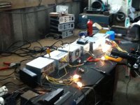
Just thought you might like to see a pic of my PC PSU charging station. Just waiting on some banana plugs for the XT60 charging lead.
 
Nicely made
How many PC PSU ' s in there,?

Neater than mine, and this was when it was neat. I now have 5 more in series , plus another pile of twenty or so on the back of the bench

image.jpg
 
Wow you're really into it at a high level.
I didn't know you could series them like that.
I've only got one in my box, but it's a good new powerful one, that can put out more than double the watts that my icharger can use. It doesn't even get warm charging my little batteries. It's virtually silent, and with the icharger sat above it's nice big fan, the fan on that does'nt cut in so much.
 
You can only series them if you first rip them open, take the PCB out and then cut tracks/ indulate the negative lines from chassis Earth

The negative output side is isolated from the input negative internally on the board, but the mounting posts screw through the negative tracks and there may also be grounding to the input Earth.

So you have to strip and make sure that when you screw it back together the output is no longer common to the chassis and mains input wires.

If you don't,then as soon as you connect the positive output of the first to the negative of the second, you are just shorting thd output to ground.

If I want more current, I used to use the 5 volt lines as I seem to remember them giving higher current.
 
That's really intetesting.
I bet the lights go dim in your street when you fire up your charge station.
Can you series the 5v lines on one with the 12v lines on another, assuming you've done that earth/negative isolating thing ?
 
Yes, no problem as they are isolated.

I can't remember if they are current limited constant current devices or not though, so I don't think you can bulk charge off th directly.

What I did was get a Meanwell 350 -12v PSU and modify it to be variable voltage , by replacing the little board mounted potentiometer with a big external one

I CAN BUILD up the bulk of the voltage I need with PC PSU's then thd Meanwell is used in series to tweak the overall output to the exact voltage I need, and as it is a constant current PSU, also gives CC limiting
 
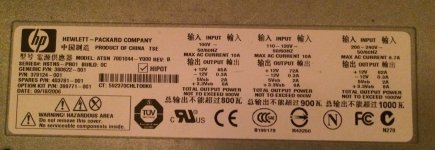
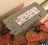
If you can find some server PSU's like these then you are in luck

I believe you are in a civilised country that allows its citizens to have 240 volt AC in the home, not like some of the colonies :wink: that only allow their citizens 110 volt,
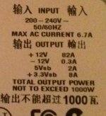
So as you can see from the label you have the potential for up to 82 amps at 12 volt with one of these.

image.jpg


image.jpg
 
I've been messing about with my controller again at the weekend, trying to find a way to get it to work with the fully charged 12s laptop cell battery, without triggering the high voltage cut out, and I've made a bit of progress.
Sort of.
I was trying to test parts of it with my DMM just to see what was different when the 10s power tool battery was connected compared with the 12s.
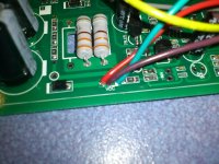
I haven't really got much of a clue, but I find the the live side of the battery first connects to the big soldered up rail that serves the FET's.
View attachment 2
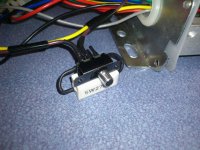
The small yellow wire that is also connected there goes up to the on/off switch on the handlebar, & when switched on it comes back in the small brown wire, & livens up the VCC rail
DSC_1295.JPG
From there it goes through various resistors and regulators to give the 5v feeds for the throttle, PAS & hall sensors etc.
It seems that whether I have the 50+v from the 12s battery getting switched to that VCC rail, or the 42v from the 10s, the other low voltages for the throttle etc stay about the same. That small green wire that's also attached to VCC, feeds the battery guage LED's on the throttle.
I checked the current draw through the on/off switch, & even with the LED's connected it is very low at about .05amps. The big current is handled in the big soldered rails, where the initial battery connection is, & that is live all the time.
With all that in mind, I thought, what if I just drop the voltage in the small brown wire, that returns from the on/off switch using a resistor. Bearing in mind that I only needed to loose about 4v, because that high voltage cut out triggers at about 46.1v, and I'd only be dealing with about .05amp, I thought a 5w 270 ohm wire wound resistor would do the job easy.
So I nipped off & got a resistor, and gave it a rough try, and it worked.
Now the controller would switch on and work the motor with the fully charged 12s battery.
All encouraged by this, I rigged it up with a switch so that I could switch the resistor in or out, so that I could still use the 10s battery withoutthe resistor if I needed to. I keep that battery in my little saddlebag as a backup.
DSC_1292.JPG
So there was me thinking I had found an ideal solution. Still had all the volts available to the FET's, Only reduced the voltage in a low current part of the circuit. And the battery guage LED's were working from the reduced voltage, so they might even still be usefull.
Felling very pleased with myself, I put it all back together, put a cold beer in my rucksack, and set off for Mooloolaba.
Bummer!
As soon as I got round the corner and gave it a bit of throttle expecting 50v worth of supercharged boost, all I got was a little gentle shove. Same with the PAS. Just as if I was only using level Half assist, if I even had levels.
Still went and sat by the river and drank my beer, but it was more like drowning my sorrows than celebrating.
I switched out the resistor, and came back home on the power tool battery. At least that still works as usual.
Can't understand why it's not getting hardly any throttle or PAS. The 5v feed for those is still there. Must be something more complicated going on in there, than my simple mind can grasp.
 
And how did it work on the way back when the voltage had dropped and resistor was switched out?
Was it back to normal?

If it is normal, then your idea may work with a slightly approach.

All I can think is that the resistor is fine dropping the voltage under no current, but as soon as you draw current, the voltage drop is too great.... so

Maybe rather than a resistor see if you can look up basic voltage dropper / regulator IC's Maybe something that can give the voltage drop you need while maintaining required current without excessive voltage drop.
 
I seem to remember on the Lyen /Xie Chang controllers had a resistor R12 that you had to mod for higher voltage use

Stick this, as is, in to google search to let Google search the forum for R12 mod threads

R12 mod site:http://endless-sphere.com/forums


See if there happens to be an R12 resistor on your board and if it is in a similar location. If you do find one, try tracing both ends of it.
See if one end goes direct to one of the pins on the MCU chip.
If it does you could try modding that,
Try and read it's code, look up its value, then calculate a parallel resistor to drop or increase its value by a small amount, maybe just 5 or 10 %

If you could ramp up your voltage slowly BEFORE you do the mod, and note the exact HVC,
Then see if the mod changes the HVC and work from there.
 
Back
Top