New member taking the plunge with an eBay kit

Going home with the resistor switched out using the 10s battery was fine. Just like normal.
When I worked out what resistor I was going to go for yesterday, I tried 1kohm ones in parallel at first, because that was the lowest value I had in my box of bits. They were only little quarter watt ones, and when I only had one or two together, with a full 12s battery, they were getting pretty hot. It took 4 of those in parallel to get the voltage down to below 46v.That made 250ohms.
The nearest to that, I could buy in the 5watt ones were 220, or 270, so I got both. I tried the 220 first, but it was still too much volts, and it wouldn't go, but the 270ohms did the trick. I did try hooking the motor up to see what current I was pulling through the on/off switch, and with it running, I only got max .06amps. I should have checked the voltage on the controller side of the resistor at that stage. Maybe I'll try doing that next.
I might have an LM317 in my box, I think that's adjustable, but I think it will only go up to 37v. Thats a big drop from 50v, so I expect it would need a pretty good heatsink.
Also it has to have a supply voltage at least 3v over the output, so it would only be useful down to 40v battery voltage.
I'll do a bit of poking around, and see if I can find a more suitable voltage reg IC.
I tried searching R12 Mod & R12 on the forums, and didn't get any hits.
 
BMboomer said:
I tried searching R12 Mod & R12 on the forums, and didn't get any hits.

you wont, site search is near useless, that is why I said

NeilP said:
Stick this, as is, in to google search to let Google search the forum for R12 mod threads

R12 mod site:http://endless-sphere.com/forums

Doing that brings up many threads, pages of search hits on the endless sphere site, with the R12 mod mentioned in the thread.

copy and paste all in red, as it is in to a new google window and you will see. Or open a Google proper search page and go to teh Advanced link and put in the terms in the top box, and the endless sphere forums URL in the Site box...does the same as I wrote in red.
 
https://sites.google.com/site/shelbyelectro/controllers-and-electronics/controllers/infenion-high-voltage-regen-r12-mod
 
Done it!
I had another go at checking voltage after the resistor when it was going, and it was much lower than expected. So I tried temporarily paralleling what I had at hand, and just by trail and error, I found that a 180ohm one with the 270 that I already had seemed very promising. That works out at 108ohm. I don't know why I couldn't make the 220 one work yesterday, but those two work with a full battery.
So I soldered it on, and put it all back in the frame bag, and just gave it a try for about 5km with no pedaling at all, and it goes great. When I got back I checked, and the resistors and battery are warm, but not hot. Controller feels ok too, so I'm real happy with that.
I tried the Google link you gave me about the R12, and there is loads there to read. thanks for that.
DSC_1310.JPG
 
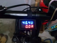
Had a much bigger ride today with the resistors switched in, about 12km with virtually no pedaling. Got the 12s laptop batteries down from fully charged to about 45.5v idle.
The bike went really well. plenty of power the whole time, and nothing overly hot when I got back. Motor was barely even warm. It's really quiet, and freewheeling is not a problem at all, like I thought a direct drive would be.
I just snagged some more of those laptop batteries with the Samsung 2600mAh cells, off of Ebay, for $10Aus a pop this time. That makes them less than $2 per cell. I'll keep going with 12s, with a few more parallels.
 
dnmun said:
no idea of what those big cement resistors are doing there.


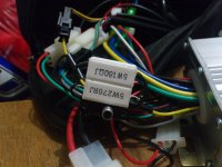
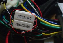
What the ones I circled in red?

They are BMboomers method to defeat the HVC

This controller has a HVC cut out, so when he connected a 50 volt battery pack it cut out. It seems in this controller the HVC circuit is fed from the feed that comes off the ignition line.

So what he has done is put a 108ohms resistanc after the switch, so the HVC circuit is being fed from a slightly dropped voltage, from after the resistors.

In the past with the known Xie Chang controllers I don't believe there was ever a HVC. Yes there was an upper regen limit but nothing to stop the controller from starting.


circled.jpg


This controller would not start above a certain voltage..so his method was to drop the 50 volt through the switch down to a level that allows the controller to start,

the Mosfets are still being fed via the main 50 volt in, it is just the MCU and HVC side that is now being powered via the resistors.
 
so there is full battery voltage on those resistor legs in that red circle? is there a fuse anywhere even? whose idea was this anyway? what is wrong with just changing the resistor divider?

has it even been proven that the controller has a HVC or if it is just shutting down from overvoltage to the regulator?
 
dnmun said:
so there is full battery voltage on those resistor legs in that red circle? is there a fuse anywhere even?


Full pack voltage, but exactly the same as any ignition switch and as for a fuse, well only if there is one in the standard battery line. Consider that there is normally not a fuse in the ignition line any way, it is no great difference from a standard ..apart front the bare wires on the resistor legs !!

dnmun said:
whose idea was this anyway? what is wrong with just changing the resistor divider?

BMboomer came up with it, a damn good alternate to trying to find that resistive divider network if you are not fully conversant with these controllers. We have not yet determined if this is a XieChang controller or not. From memory the HVC mod is the R12 mod .....yes? that is the route I pointed him down to start with. It was suggested to find the divider network, but he seems to have come up with this easier and less SMD / board orientated solution

dnmun said:
has it even been proven that the controller has a HVC or if it is just shutting down from overvoltage to the regulator?


Well reading from what he has posted, on the previous page of posts, about 5 posts up from the bottom, it seems that the voltage regulator is not shutting down, It produces near enough the same voltage on the 5v line wether fed with 46v or 50. Just that at 50v it does not run, so to me that hints at it being HVC shutdown.

I would had have continued with pursuing the finding of the divider network, or trying to ID this board exactly and see if it already has been found. The early EB2xx boards were dark green I seem to remember, but i can't recall if they had the same R12 mod and if they had a HVC cut off or not though..can you remember?
 
i thought i told him where to find the resistor divider. it will be between the input voltage and ground along the bottom edge of the controller. the middle of the divider will have a trace running over to the micro. i thought i had explained that already. maybe another thread.
 
Yes it was explained to me, and that was what I was trying to find with my DMM when I came up with this Idea. I am only very basic with electronics, and I wasn't really sure what dnmun was on about. I don't really know how to recognise the resistor divider specially on this SMD board.
The resistors are a bit big, probably a bit of an overkill, but I wanted to be sure that I didn't get any heating problems.
It was just an experiment really, and a bit of trial & error, but it's turned out to work really well. If I'd known what was what, I wouldn't even have needed to open the controller up to do it.
Those bare bits of resistor lead, are going to get made safe. Now I've got it all working properly , I'll enclose the whole thing in heat shrink tube, and cut a little opening for the switch. I have had insulating tape wrapped around them during testing.
Another nice thing about this method,is that I can just switch the resistors out if I want to go back to my 10s backup battery.
I have got a fuse in the main battery lead.
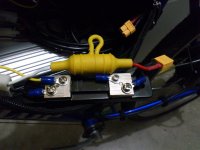
I have had my shunt resistor for the amp part of the volt/amp meter delivered now. I fixed that up this evening, and went off for some more testing, and its all working great. I was worried that the shunt resistor might get hot, as it has to pass the whole current draw, but it doesn't even get warm.
I don't know how accurate the ampmeter is, but when the motor was pulling hard I saw over 20amps a few times. On a fresh battery that was sagged down to about 47v at those times, that would be over 900 watts. If thats right, it's not suprising that it goes well. Considering that the original kit was supposed to be 36v 500w, I think it's doing really well, with nothing getting hot, specially not the motor. That barely even gets warm.
when I'm up to speed on flat ground it's pulling about 5 or 6 amps. It doesn't make much difference if I pedal when I'm going along like that, because even in top gear, I can't pedal fast enough to keep up.
Here's some pics of the Volt/Ampmeter after tonights testing, and the new shunt. By the way, that will get the heat shrink treatment as well.
DSC_1314.JPG
DSC_1313.JPG
 
if you go back and look in your first picture there is a resistor divider with one end connected to the thing labeled Vcc that is where you have to focus. you need to look at those little surface mount resistors and figure out that bridge and then change it for the higher HVC setpoint if you cannot reprogram it.
 
VCC is what gets fed with battery voltage through the brown wire returning from the ignition switch. Pretty much everything on the circuit board except for the Mosfets seems to get fed from there, including the battery gauge LED's.
That brown wire is where I have reduced the voltage with my external resistors. At first I put too much resistance there, and it didn't go well under load. NeilP pointed me in the right direction, and I tried some others in parallel to reduce it, and the 108ohm I've ended up with there seems to be just right.
At the left end of that VCC track, there is a black surface mount thing with M7 on it. I guess that is a diode. Above that there is what I think are three resistors in series. The top end of those has 13.4v, whether I have got 12s with or without my resistors or 10s connected. The top of those big resistors has 13.4v also. The bottom of those has about 15v.
If I have 12s connected, & it won't work because of the HVC, those big resistors got quite hot, but not so if I have my external resistors switched in, or if I only have 10s connected.
The little 5v Voltage Reg just to the right of the big resistors, works fine whatever batteries I have connected. All the low voltage supplies to the throttle & PAS etc are all also fine. even when the HVC is triggered.
If I managed to find the right resistor on the board, that controls the HVC, and was going to change it to a higher value, it would mean desoldering it, as putting another one in parallel would only lower the value. I don't really want to start messing around with surface mount soldering. Also trial & error of the values, would be much harder to do at the circuit board level.
What I have done, has tackled the problem at it's source, with a few nudges in the right direction from you guys.
It's made the whole thing seem like it's getting a lower voltage,except where the full voltage is really needed at the Mosfets.
It doesn't look too pretty at the moment, but this bike is just a test bed. When all the snags are ironed out, I'll put it all on a better bike, and make it neat.
I'm quite happy with how the HVC fix is working now, & the next thing I want to focus on is the PAS.
As it is comes with this kit, it's all or nothing. no levels of assist.
What I am experimenting with at the moment. is a potentiometer, wired into the return (green) wire from the PAS sensor.
I don't know if I'm on the right track yet, or if the controller will still just deliver full power whenever it gets any signal at all.
If it doesn't work, I could try putting it on the supply (4.3v) side of the PAS.
Failing that, I could try joining the PAS signal into the throttle signal input on the controller, either with or without the pot.
I've rigged it up temporarily, but we're getting some rain here at the moment, so I can't try it yet.
I'll keep you posted.
DSC_1315.JPG
 
If you did find the resistor divider pair, then putting a resistor in parallel with it was the R12 modification, yes you do lower the value.

Imagine two resistors in series. I am only using easy numbers, these in no way reflect what the figures on the board will be.

So you have two 5 Ω resistors, in series so 10 Ω total with 10 volts across them both, so using Ohms law V=IR I= V/R that is 1 amp flow.

if you measure the voltage at the middle point it will be 5 volts. each resistor drops the same voltage

Now imagine your HVC is measured at that centre point and it is set at 4 volts..so 5 volt is too high. so you need to change either one of those resistors to a value that alters the voltage at that middle point to a lower voltage. You need to drop more voltage across the first resistor..OR less across the second.

the ratio at the moment is 5:5...1:1 and you want 6:4, but don't want to change either SMD resistor

So if you drop the value of the lower resistor by 4/6ths to 3.3ohm

Overall resistance will now be 8.3 Ω and current flow will be 1.2 amps.

this will give a voltage drop across the first resistor of 6 volts and cacross the second of 4 volts...so the centre pint voltage will be 4 volts.


So now all you need to do is calculate what resistor you need to parallel across the second resistor to make the 5 Ω drop down to 3 Ω

which wold give a resistance of about 9.7 Ω across the 5 Ω.

http://www.sengpielaudio.com/calculator-paralresist.htm


The R12 mod on many boards was easy because there was a hole nearby where one end of the parallel resistor could be soldered..and the other end went to any convenient ground trace.
 
they are all surface mount resistors from looking a that picture so it only requires changing one of those SMT resistors. or soldering another one on top of one of them. the SMT resistors are much cheaper and less risk of shorting over them big cement power resistors. which function only to starve the voltage regulator of juice.
 
Do you think that this voltage divider that you're talking about might be those 3 resistors, that are in series, that have vcc voltage at one end, and 13.4v at the other end, just to the left of that empty space that's alongside the 2 big resistors?
Changing the subject to the PAS. I've tried it now with the potentiometer. It didn't work well on the green signal wire coming back from the pedal sensor. It was still all or nothing like before.
I tried it next, in the supply wire to the pedal sensor, and that worked much better. I only had a 100kohm potentiometer to hand, and I had to have it turned way down for it to work at all, and because it's much to high in value, it is difficult to fine tune. Anyway I got it to a setting that now starts giving assistance in short bursts as you build up speed on the pedals, and turns into continual assist, by the time you get to a decent cadence. like someone giving you little shoves while you are getting going. It's not perfect, but it's much more usable than what it was. At least it comes in more gently now, and its possible to use pedal assist when you're just cruising around in slow situations, without it keep taking off like a scalded cat. When I got home I checked what resistance I had the Pot set at, and it was only 35ohm, so I'm going to get a much lower value one, and do some fine tuning. It works well with the lower gears, going up hills, because the higher pedal cadence translates to less coming and going of the assist and it becomes continuous at a lower road speed. If I could smooth out the coming and going a bit as I'm building up speed, it could be made to be pretty ideal. maybe I'll experiment with a capacitor in there somewhere.
 
yes the divider is on the edge of the board and is between Vcc and ground. the voltage on that trace that comes off and goes over to the microprocessor is what you need to adjust by changing the resistor values in the bridge divider.
 
I don't think you will find that approach will work at all for the PAS

The PAS ( unless radically different to any other) is merely a hall sensor mounted near the crank with a plastic ring of magnets, usually 6 or 12.
The hall sensor needs its 5volt to operate, and it outputs 5volt pulses.

Pretty sure these pulses are NOT used like a throttle signal. They are merely counted by the controller, and assistance is given after a certain number of pulses are received by the controller. That assistance is full power or none at all. Which is usable on a low power system but not on a bike with higher levels.

I guess the perceived effectiveness you are seeing is due to variances in different magnets strengths in the ring. When you are powering the sensor at a lower than optimal
voltage, or putting resistance in the output it is just messing with how often it produces a pulse big enough to be counted by the PAS system

So... Various approaches
Try the PAS tamer from em3ev web site that I posted earlier in this thread. That connects to your PAS wheel BUT not to the PAS input on the controller. It T's in to your throttle signal wire between throttle and controller. It needs a power supply too, 36 or 48v units available. Should be fine at 50volt. What it does is convert the pulses to a variable throttle signal. It is not unfortunately proportional, it too is either on or off BUT the big difference is it outputs a different throttle voltage,depending on which level it is set at. 5 levels (off,1,2,3,4)

Second is go out and buy a Cycle Anslyst V3 and associated PAS and or THUN torque sensing BB. But that will probably cost as much as your kit by itself

Third approach is to see if you have pads on back of the controller labelled X1 & X2,( maybe X3) if so, they may we'll be speed switch pads. They are often speed control pads. Shorting one or the other to ground gives a speed change if the controller has been programmed with speed settings. Neither pad shorted gives speed 2, X1 gives slow, X2, fast and X3 gives reverse. But trying this could also short out and destroy the 5 volt regulator if these pads are present but not designed for speed in your controller.

If you really wanted to be flash, you could start reading up on digital to analogue convertors and build yourself something that takes the 5 volt hall sensor pulses and produces a throttle voltage proportional to the speed.
 
You can't put a pot on the PAS signal to reduce it. The controller only sees and acts on yes or no. The reason you get bursts of operation is because you're on the boarder of yes and no having turned down the 5v.

There's a king meter led display that can integrate PAS and throttle to give three levels of PAS. I can't remember the number, but it's the kidney shaped one. I've shown pictures of it before, so if you search for the right terms, you might be able to find it. Try "throttle integrate PAS".
 
Yes my further testing, and messing about, all seems to be to be having results that are very much like what would be expected, from your very helpful explanation of how this PAS works.
In short my experiments with this are very hit & miss, and not very satisfactory. What seems to be working to some degree on one ride, doesn't work well at all on the next.
I went for a ride with my wife riding in front this morning, on her normal bike, and I had it adjusted with the finer 1k pot to give me very small pulses, but every now & again, it would do a big one, and I'd have to hit the brakes to stop running into the back of her.
Looks like I might have to compromise my idea of keeping it really cheap, if I am to get a really good PAS working, or just carry on tootling around on the throttle.
At least doing it that way, I can keep the amps down to where they should be. Those 20amp+ bursts are not good for my batteries, as they are at the moment with only 2P.
I should be getting some more delivered next week, and will be able to parallel them up a fair bit more.
I'll have a look at those other approaches you mentioned, but I don't think I'll be getting into a Cycle Analyst just yet.
 
Got a workable solution to that one now, although I'm still interested in trying to gain an understanding of the more elegant ways that you guys work around that particular snag.
Looking back over this thread, some of the stuff that I didn't even understand at all in the earlier posts is starting to make more sense to me now.
I thank you all for your help and patience.
 
Back
Top