Open Sensorless BLDC controller

walls99 said:
casainho said:
Could you please explain your BEMF circuit, logic behind it? How do you use the output of this circuit in the firmware?

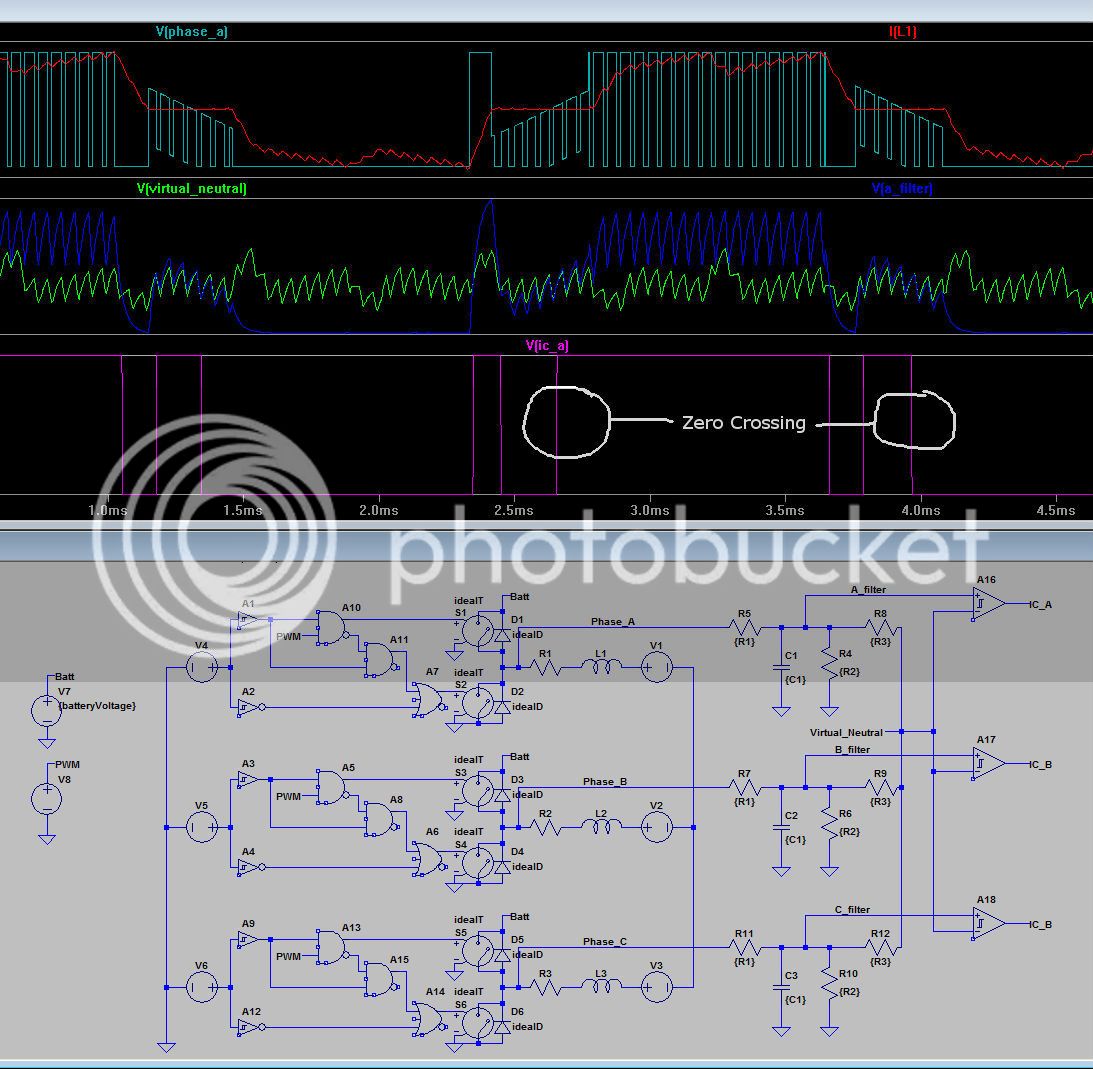
The BEMF circuit is a standard voltage divider + low pass filter + virtual neutral comparator for Zero Crossing detection feeding the Input Capture module of the PIC. There is a lot of literature available about the Zero Crossing principles. I suggest you read this 2000+ post thread DIY BLDC controller.

The low pass filter is designed to limit the phase lag to below 30º for the maximum RPM, so it can be compensated for by adjusting the phase advance in software. I also make use of the PIC digital noise filters to reduce the interference from the PWM signal.

See attached, the BEMF filter LTspice:
Thank you for this information. I did read something about using the PWM OFF time to read directly the Zero Crossing.

Right now I am experimenting to learn and be able to detect the rotor position, using the current sensing as you described. Later I need to implement the startup strategy.
I found that one parts of mosfet drivers are not working as expected (much slow turn on) and I need to find why. A big change is that my ARM works at 3.3V and the original controller worked at 5V, so, the drivers may need 5V logic.

Hmm, I don't know about spice simulation... is there any OpenSource software for it? (I am limiting myself to OpenSource software).
 
Hey Walls,

I am finding this thread very educational and learning a lot from it. Your design makes my DIY sensored BLDC controller look like a broken toaster.... :mrgreen:
I'm just starting to understand sensorless detection methods. Can you give a short explanation on your BEMF detection design?
The analog circuit is straight forward and I understand it well. The FW implementation is new to me.
Do you sample the comparator outputs when PWM is low? What digital filtering are you implementing?
I read a Microchip app note about majority voting algorithm and FIR filtering...what do you use?
Keep posting and updating..

Thanks,
S.B.D
 
S.B.D said:
Do you sample the comparator outputs when PWM is low? What digital filtering are you implementing?
I read a Microchip app note about majority voting algorithm and FIR filtering...what do you use?
The comparator outputs are "sampled" continuously by the Input Capture module independently of the PWM signal. Interferences from the PWM are filter out by the analog low pass filter and the digital noise filter integrated in the PIC, check section 16.3 of the 18F4431 datasheet for more info.

In running mode, the Input Capture is only enable for the comparator output you expect an event from and only from 15º before the expected zero-crossing until it happens or time's out. see the function below for more info on the Input Capture setup depending on the step/position:

Code:
LOAD_IC     org 0x1000
 
Walls, could you please share with us some pictures from the simulation?? Maybe some pictures can help us learn how it works... like I am curious to see the result signal after the filter and input to microcontroller.
Thank you.
 
casainho said:
Walls, could you please share with us some pictures from the simulation?? Maybe some pictures can help us learn how it works... like I am curious to see the result signal after the filter and input to microcontroller.
Thank you.

Here is the LTspice model based on Bearing's model:
View attachment motor_sim_0.4.zip

And the picture:
ZC_sim2-1.jpg
 
Nice!
I'm happy someone made use of that spice model. I see you have made some enhancements too.
 
Progress update:
- PIC clock increased to 40MHz do to more stuff per 50us PWM cycle.
- Implemented and tested temperature monitoring and management for the mosfets
- Implemented regenerative braking
- Stress tested with 90A phase current accelerations up to 4600RPM (~1900W) then 40A regen braking

See below the battery current, voltage and power during the stress test. Note that regen current appears as positive:

StressTest_90A_40A_4600RPM_05MAY12.png


Todo:
- Test on my Goped...
 
walls99 said:
Todo:
- Test on my Goped...
6km of road testing later, I'm happy to report that the controller is working well!

The top speed is 34Km/h as expected. Regenerative braking is also working but the fixed braking phase current makes it too aggressive at speed, so I probably need to control to power rather than phase current to have a more progressive braking experience. However it does feel great to know that some of the kinetic energy is returned to the battery rather than being wasted in heat in the brake disk!!!!

IMG_1161.jpg
 
just exceptional, really nice thread to follow your progress.

i would request you change the title to "open source BLDC motor controller" so it will come up more rapidly on google search since it is the more commonly used term.

really really nice.
 
walls99, great news!!

Will you design a PCB for this controller? I would use if it could control my 24V 250W electric bicycle. I could buy the components, assembly and test my board.

Why don't you put the firmware and schematic/board sources on Github (as other Open Source projects)??

dnmun said:
i would request you change the title to "open source BLDC motor controller" so it will come up more rapidly on google search since it is the more commonly used term.
Good idea but I would also use the words "ebike" on the title for the same reason.
 
casainho said:
Will you design a PCB for this controller? I would use if it could control my 24V 250W electric bicycle. I could buy the components, assembly and test my board.
Why don't you put the firmware and schematic/board sources on Github (as other Open Source projects)??

I have designed a custom PCB for my Goped controller, see pictures below. I'm happy to share the design with other who want to use it as a starting point but I wouldn't recommend a straight copy of it.

Untitled-2.png


Untitled.jpg


Untitled-1.jpg


Untitled-3.jpg


IMG_0120.jpg
 
Walls I frocking love it!!! Thats easily more powerfull then a 12 fet with 4110s!
 
walls99 said:
I'm happy to share the design with other who want to use it as a starting point but I wouldn't recommend a straight copy of it.

Here are the schematics and board layouts for the brain and brawn of my controller. I have updated them with all the changes I made on my prototype, so use them at your own risk.

View attachment 1

brain_40.png


View attachment Hoverboard_blmc_brawn_40.zip

brawn_40.png
 
Hey, thanks for sharing!!

I am planning to buy the components and assembly by hand on a perfboard the power section. I really like the modular way of the system. I also want to use the ARM processor/board I am familiar with and program in C instead of assembly.

I also want modular because I plan to use bluetooh UART module.
 
walls99 said:
I have corrected a few bugs and enhanced some on the synchronization loops to be more stable, please find the updated source code below:


Change log:
  • Fixed throttle range in non car mode, 1.1ms = 0 and 1.9ms = 100%, new sync algo in ZC locked state,
    Made brake mode optional, new sync algo for RC locked state, new filter for RC input.

Is this the latest version of the projekt?

I would like to play with this, and then maybe make a board which can drive a 80100 on 80V.
 
bearing said:
Is this the latest version of the projekt?

I would like to play with this, and then maybe make a board which can drive a 80100 on 80V.

No, it's quite out of date. I'm planning on releasing new soft but I haven't had the time to finalize everything I wanted. They are many upgrade to handle "high power": Torque control, automatic advance timing, sensorless startup, temperature control, regenerative braking...

I've sent you a PM to discuss alpha release, if you're interested?
 
walls99 said:
bearing said:
Is this the latest version of the projekt?

I would like to play with this, and then maybe make a board which can drive a 80100 on 80V.

No, it's quite out of date. I'm planning on releasing new soft but I haven't had the time to finalize everything I wanted. They are many upgrade to handle "high power": Torque control, automatic advance timing, sensorless startup, temperature control, regenerative braking...

I've sent you a PM to discuss alpha release, if you're interested?
Walls99, please share your code on github. There you also have a wiki were you can place the information. Thank you.
 
hi walls99,

i would like to make a similar inertia dyno for some controller testing.

what material did you use for the flywheel? i would like to use MDF, but i am a little concerned with the centrifugal forces and the flywheel breaking.

very cool project btw!
 
nieles said:
hi walls99,

i would like to make a similar inertia dyno for some controller testing.

what material did you use for the flywheel? i would like to use MDF, but i am a little concerned with the centrifugal forces and the flywheel breaking.

very cool project btw!
Hi Nieles,
I used 16mm particle board, I'm sure MDF would be fine too, probably better from the balancing point of view. I wouldn't worry about the flywheel breaking but your motor mount! At speed >1000RPM I really had bad vibrations, as seen in the video due to the lack of balancing of my DIY flywheel.
So it was perfect for testing start-up, low speed and regen but not good for high speed testing for more than a few seconds.
 
walls99, could you please tell me if you think the motor could work (with load, like on a bicycle wheel, starting from 0 velocity) only with current feed-back and not BEMF?

I got my motor running but without BEMF.

[youtube]9yG4NSVBGEs[/youtube]

I made some simple but interesting tests.

With 15% duty-cycle and 10ms the motor were running very slow (about 12 RPMs, motor Cute85 for 20'' wheel). But I were using the variable power supply and I could change the power applied to motor by defining the voltage supply.

(Case 1) I found that with a lower voltage, like say 15V, the motor don't turn or vibrates/makes noise/small turns. (Case 2) If I rise slow the voltage it starts to turn up to a velocity which seems to be perfect (but slow due to the 10ms), no noise, no vibrations. But if I brake the motor with the hand, it starts to vibrate/make noise and stops...

(Case 3) Continuing, if I rise the voltage (without braking the motor with my hand) the motor starts vibrating/making noise again but this time rising also the current/power used!!! Then I tried to brake and it stopped to make noise/vibrations but the current still high. I had a bit difficult to brake and stop the motor. I rise again the voltage and keeping brake the motor, until I found I couldn't no more brake it!! it turns with strong power, no vibrations nor noise.
 
casainho said:
walls99, could you please tell me if you think the motor could work (with load, like on a bicycle wheel, starting from 0 velocity) only with current feed-back and not BEMF?

I got my motor running but without BEMF.

I made some simple but interesting tests.

With 15% duty-cycle and 10ms the motor were running very slow (about 12 RPMs, motor Cute85 for 20'' wheel). But I were using the variable power supply and I could change the power applied to motor by defining the voltage supply.

(Case 1) I found that with a lower voltage, like say 15V, the motor don't turn or vibrates/makes noise/small turns. (Case 2) If I rise slow the voltage it starts to turn up to a velocity which seems to be perfect (but slow due to the 10ms), no noise, no vibrations. But if I brake the motor with the hand, it starts to vibrate/make noise and stops...

(Case 3) Continuing, if I rise the voltage (without braking the motor with my hand) the motor starts vibrating/making noise again but this time rising also the current/power used!!! Then I tried to brake and it stopped to make noise/vibrations but the current still high. I had a bit difficult to brake and stop the motor. I rise again the voltage and keeping brake the motor, until I found I couldn't no more brake it!! it turns with strong power, no vibrations nor noise.

It looks like you are running in open loop, so this is the expected behaviour. This mode of operation is not really usable as you can't control timing or torque, however it's a good 1st step to understand brushless motor control :)
BEMF sensing/timing and close loop control is the logical next step but it's also more complicated. Using only current feedback is possible but a lot more complicated, see FOC theory.
 
walls99 said:
It looks like you are running in open loop, so this is the expected behaviour. This mode of operation is not really usable as you can't control timing or torque, however it's a good 1st step to understand brushless motor control :)
Yes! I need to feel to understand.

walls99 said:
BEMF sensing/timing and close loop control is the logical next step but it's also more complicated. Using only current feedback is possible but a lot more complicated, see FOC theory.
I would like to work on a robust start-up scheme. I read about yours (you shared before on this post) but my hardware lacks a current sensor, it just reads very high current value (probably the maximum current). Could you please share your thoughts about this system that don't reads current, only the maximum? how do you think it works? PLEASE see my controller schematic PDF and here more info about the controller.

Could you please share your thoughts about the BEMF circuit of this controller?

Since the controller don't have current sensor, I am thinking in trying to start-up the motor by making it rotate at slow and constant speed (10ms commutation in my motor) and going increase the duty-cycle up to get rotation/signal of BEMF. I must care about maximum current or I may miss the BEMF circuit but short-circuit the motor with maximum current/duty-cycle. What do you think about this idea?
 
Back
Top