Open source BMS for 48V to 400V lithium-ion battery pack

The SS is not intended to be a single port BMS it has separate charge & discharge paths.

-There is only one UART, use CAN instead.
-Yes I2C can be used for IO expension
- Using 2 OZ in copper at least for enabling higher current
- Some high power surge wirewound resistor do exist for precharging. Mounted on the PCB
- Yes many external current measurement is possible with I2C adressing
- Using 58V rated fuse, not 32V
- Tested the fuse to a certain limit with up to 20S packs, the fuse still does it's job, but it is not intended to be a perfect solution either. Some specialized fuses can be more expensive than this BMS
- SS is intended to be used for small battery pack in LEV, there is Master-LV for larger battery pack. TVS on the board as well to limit surge voltage during a short. TVS are SMB size, so you can guess the approx. inductance limit for the TVS to bring protection.
- Not open source hardware
- Loose wire detection can be triggered with manual command for checking the BMS. Other safety commands are done in the main loop.

The SS-lite had little demand and now that the firmware allow the smaller XLITE do get pack current reading over CAN bus, there was little reason to keep the larger SS-LITE. It can still be produced upon request
 
Correct me if I'm wrong, but separate-port BMS requires the load devices to be kept on separate circuits from the chargers.

IOW you cannot use combi inverter-charger devices like MultiPlus.
 
I haven't read through all the pages here so pardon me if this has been mentioned but although not open source I don't see Batrium mentioned in this discussion. Pretty much belongs in any discussion where powerwalls come up.

https://www.batrium.com/

undefined
 
Yes, those batrium system seems to be better oriented toward solar/storage application. The web app user interface is nice for remote viewing and wifi is included. Their hardware seems to offer quite a large cooling capacity for balancing large packs.

The BMS hardware presented in this thread so far have been mainly oriented toward electric vehicle application.
 
Thank you a lot for ansering! Also t:)

ENNOID said:
The SS is not intended to be a single port BMS it has separate charge & discharge paths.

Thank you also for pointing out that my thought "BF1 = 32V" was wrong. Okay littelfuse is known to make confusing TVS-diode order codes as well :evil:. If I was them I had named them BF1-32 BF1-58 8). A single piece price of 4 USD is nice, of course. But the rupture current of 1kA is would mean a impedance of 50mOhm would be required for a safe blow. I guess this will be undercut, so I will have to look for other solutions insted

ENNOID said:
- SS is intended to be used for small battery pack in LEV, there is Master-LV for larger battery pack. TVS on the board as well to limit surge voltage during a short. TVS are SMB size, so you can guess the approx. inductance limit for the TVS to bring protection.

I was under the impresssion one would also use a specified save avalanche region within the switching FETs?

In my job I have seen some HV-system contactor boxes become quite black, molten metal and arcing at places we never had expected when arc could not be extinguished properly. Just to understand why I am so weary about those things. But I do not have any experience in LV-battery packs.

Because of the split charging/discharging ports I will have to look further, I guess. I don't have access to nice.
I'd also like to encourage you to include the open-wire check into the main loop. Maybe with detection times of 30s and 2:30 debounce or so. I have worked with LTC6812 and seen some strange things happening to battery modules if vibrated long/strong enough. And OW does not take much time at all.

Thank you again, for your work!
 
Eventually I will offer something more specific to solar/storage, but I don't really have enough experience with solar yet. I installed solar panels for first time at home this year and I'm planning to add some storage capacity eventually and start playing with the idea. I'm not living in an area where solar make sense at all. The problem with the Master & slave boards config for energy storage is, I think, mainly the power hungry contactors. Some other details such as wifi & web interface are also missing, but the actual firmware is quite good for it with maybe a few solar oriented optimizations here and there and some new CAN bus protocol to be compatible with most other devices.

I'm curious if anyone here could propose some clues about which solar hardware solar inverter/charger should be supported first?
 
Here's the issue with solar and off grid right now that I think poses an opportunity for you:

All of the all in one systems are 48V unless you spend big money and have a predesigned 384V battery.

This leads to inefficiencies, but it's cheaper to setup batteries that way. All of the off the shelf BMSes (i.e. JK etc.) are 24S max total and the inverters are 16S max total. And if you want to expand the system you have to add more inverters and more BMSes all in parallel.

The ideal system from my perspective is one that can use your BMS design and take a 16S lifepo4 as a start with a single slave, and hook it up to an inverter and a MPPT solar charge controller.

Then, if they need more power they can add a second slave and up the voltage to 96V nominal and the inverter just handles it because it's designed for 200A output and the MPPT just handles it because it's designed to handle 1000V incoming.

Etc. up to say 128S (384V)

The system just expands and scales as you add to the system and the MPPT just requires that your panel voltage is say 10% above whatever the pack max voltage is.

So your current system works pretty well, especially if it had active balancing and could bypass the positive side and send that directly to the inverter. Then the key would be able to add a scalable high frequency inverter (i.e. that can handle anything from 48V to 440V input and output 240 @ whatever amperage and say 6500W (10kW would be ideal as this is easily handled on 280ah LiFePo4 batteries) per 48VDC on the battery pack.

The MPPT would be pretty straight forward and if it could be a multi-phase or use SicFETs to handle 1000V at 32A then scaling the system means a single MPPT could handle the entire thing to big power.

And then the final thing would be AC to DC charging that was isolated and could use the grid.

I see these all going into a rack as 1U units except for the batteries themselves (which now they're starting to sell the rack mount battery boxes separately)

The next wish list item is Telsa DC/DC (not fast) charging that bypassed the inverter and went directly from the battery bank. The protocol is out there (it uses CANBus) and this would be huge for people with solar because then they wouldn't need a huge inverter and they'd get 15% more power because of the elimination of losses going DC to AC to DC and going DC to DC at 98% instead of at best 80ish%.

And the final wishlist item is a DC/DC heat pump unit that can run off of 384V and would step up 48V+ to 384V as needed. But that's a bigger conversation. (side effect is about 8-10% more efficiency for heating and cooling houses though so it's worthy of conversation)

This would be a highly marketable system too because with UL listing on the AC/DC Charging, this could be an incremental system.
 
I'm just asking for what is the inverter/charger that should be supported first via CAN bus or modbus with link toward their protocol and product...
 
JohnGalt171 said:
Then, if they need more power they can add a second slave and up the voltage to 96V nominal and the inverter just handles it because it's designed for 200A output and the MPPT just handles it because it's designed to handle 1000V incoming.

I just want to state: Don't underestimate the challenges to overcome designing for such voltages, currrent capabilities and especially the range of input voltages you're thinking about. The latter will make the system excessively expensive at lower voltages (not attractive to start with in the first place) and the former, especially arc burning, will burn down your house.

Take special care of line inductances and the working direction of common contactors in which they might be able to interrupt a "soft" short. Once. In their life time. Keep track of contactor health. Also, you'll need proper isolation monitoring of for example symmetrical isolation faults - which are not that easy to detect and quantify with reasonable accuracy. And that's just the beginning.

There's reasons why whole company departments need years and a lot of experience to design HV-Systems like these. The devil is in the details not, the obvious stuff. :)
 
This is why I'm not jumping in this stuff. It just looks like an infinite list of unobtainable requirements...

I will start only implementing CAN bus protocols for now and slowly ramp up new features oriented toward solar/energy storage
 
Hi, I am building a 26s battery that will output 350 to 400 amp for motocross racing and looking for a bms. I’m using a Vesc controller and found that it can receive data from bms over canbus. Then I found ennoid but for my application the best would be to have a bms that does not have a contactor because if the bms trip on a jump it will result on a crash. A soft rollback of power would be the best solution and the Vesc can do this. So my question is could I use two of the charge only bms to get 26s and let the controller rollback the power instead of having a contactor that act like an on off switch?
 
I haven't yet experimented with two XLITE-V3 over CAN bus yet, but yes that is likely the way to go with a 26S pack.

XLITE-V3 now has an isolated CAN bus IC and a Bluetooth module which are now fully integrated with VESC ecosystem( CAN & BLE).

VESC mobile over Bluetooth is very nice for BMS configuration, data monitoring, firmware updates, etc.
VESC tool desktop can also be used for the XLITE via CAN or via VESC mobile wireless bridge.

Power rollback is done by the VESC itself based on the cell temp and the reported SOC.
BMS only supply the data and the VESC decide how to handle the rollback based on the BMS configuration.
Settings in VESC are basic but are enough. If you need more VESC has now LISP scripting.

Screenshot from 2023-02-09 13-38-17.png
 
@ENNOID What SOC calculation differences could you observe between your master-slave BMS and charge-only BMS solution?
 
ENNOID said:
I haven't yet experimented with two XLITE-V3 over CAN bus yet, but yes that is likely the way to go with a 26S pack.

XLITE-V3 now has an isolated CAN bus IC and a Bluetooth module which are now fully integrated with VESC ecosystem( CAN & BLE).

VESC mobile over Bluetooth is very nice for BMS configuration, data monitoring, firmware updates, etc.
VESC tool desktop can also be used for the XLITE via CAN or via VESC mobile wireless bridge.

Power rollback is done by the VESC itself based on the cell temp and the reported SOC.
BMS only supply the data and the VESC decide how to handle the rollback based on the BMS configuration.
Settings in VESC are basic but are enough. If you need more VESC has now LISP scripting.

Screenshot from 2023-02-09 13-38-17.png
Well if you could test it or be sure that two XLITE-V3 could work over canbus I would buy two!
 
SOC method is the same in V6.00 firmware for all boards.

Issue with using two xlite is related to charging. You basically need two charger, one for each XLITE/half of the pack. This is not ideal. Everything else would likely work just fine. Ideally an XLITE-30/XLITE-36 would be better solutions for a 26S pack, but that is still only an idea I'm throwing here
 
So your SOC estimates is purely based on cell voltage readout and no coulomb counting? :?:
 
c.wagner said:
So your SOC estimates is purely based on cell voltage readout and no coulomb counting? :?:

If I am not mistaken, coulomb counting is handled by the vesc controller and software.
 
A-DamW said:
If I am not mistaken, coulomb counting is handled by the vesc controller and software.
How could that reliably work, if you charge the batterie outside of the vehicle and plug it back in after fully charging it?
 
Firmware version V6.00 is using only lowest cell voltage for SOC. Coulomb counting has been disabled for this release even on discharge BMS. I will bring back coulomb couting as an option for next firmware version.
 
ENNOID said:
SOC method is the same in V6.00 firmware for all boards.

Issue with using two xlite is related to charging. You basically need two charger, one for each XLITE/half of the pack. This is not ideal. Everything else would likely work just fine. Ideally an XLITE-30/XLITE-36 would be better solutions for a 26S pack, but that is still only an idea I'm throwing here
If I understand is because the xlite is max 24s and the battery positive negative from the charger port are connected to the battery positive and negative of the balancing port? At first I was thinking of charging the whole pack from one xlite charging port but that obviously do not work. Is making a custom XLITE 30s be something you could do?
 
It is something possible to develop, but not in the immediate future. A year maybe from now.
Things can be done faster if you are a company willing to pay for faster development and need a custom board for one of your product.
 
Well I am not a company so I guest it would be quite expensive for a one off board.
I guess I could use the ennoid gen 1 for charging only. Or I could use two Xlite and use an external ant bms hooked to the charger for charging. If I go with two xlite I will need to conect the two with canbus so they talk to each other? or each would be connected to the vesc? Sorry if you find my question annoying Im new to the vesc world and all the capability of this software.
 
XLITE-12 V.2
There is SWITCH labeled socket with PRE and DIS contacts on board.
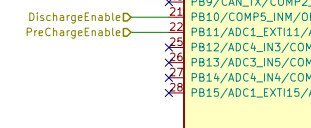
1. Manually probing, I discovered that PRE connected to PB10 and DIS - to PB11 pins of the STM32.
But, int GITHUB schematic they connected opposite: PRE - PB11 and DIS - PB10. What is right?
2. On my board DIS is connected to GND with 1.5 ohm resistance. Is it soldering BUG?
 

Attachments

  • PB10_11.jpg
    PB10_11.jpg
    21.6 KB · Views: 4
Аlso, on my board PB2 connected as DISEN, but in github version it is CoolingEnable.
 
@ENNOID
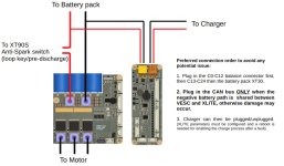
Hello, according your XLITE V2 schematic, how could I monitor Battery Discharge Current?

Current Shunt resistor connected between Battery and Charger grounds, so it is possible to measure only Charge Current.

Is it possible to adjust Firmware to use Charger socket as Load output? I.e. to switch On MOSFETS during Discharge.

Thanks in advance,
Vladimir
 

Attachments

  • XLITE.jpg
    XLITE.jpg
    145.7 KB · Views: 11
Back
Top