Probably. We went the slowest his press would go, which I think is 650RPM, and used a lubricant (I forget what it was called), but it obviously didn't help. Neither of us knows enough about this stuff yet, and I didn't research it first.Alan B said:Probably work hardened and dulled the drill bit.
You are using an out of date browser. It may not display this or other websites correctly.
You should upgrade or use an alternative browser.
You should upgrade or use an alternative browser.
Powerchair Direct Drive Brushless Motor (High-Torque)
- Thread starter amberwolf
- Start date
Neither can I! :lol:
Harold in CR
100 kW
Do you have a variable speed jig saw or sabre saw ??
Use that to saw AT the holes you need. Then, you can break off the small pieces and just clean up the holes. Had the SS manufacturing business for 18 years. Used a chunk of bees wax for a lube. Liquid runs off too quickly.
Go as slow a speed as the saw will pull the blade. You might be surprised how easily SS will cut. It's TOUGH, not hard.
Use end pieces of hacksaw blades that break. Grind them to fit the saw shaft.
Alan B
100 GW
If I remember correctly part of the problem drilling stainless is going TOO slow. There is a correct speed. Too slow heats and work hardens it. Consult the Machinery Handbook.
Grinding may work better. A dremel with a small tipped grinding stone?
Grinding may work better. A dremel with a small tipped grinding stone?
You need good drill bits.Alan B said:If I remember correctly part of the problem drilling stainless is going TOO slow. There is a correct speed. Too slow heats and work hardens it. Consult the Machinery Handbook.
Grinding may work better. A dremel with a small tipped grinding stone?
And yes every metal has a frequency, For instance when using a drill bit or a die grinder on aluminum you will see it plugs up if you try to cut to fast and if you go to slow it will just cut slow. I bet stainless is suposed to be cut slow (but I would look it up) and you should use some cutting oil to keep the bit cool so it last longer and cuts better.
I haven't had time to look up what I would need to properly drill the holes, but I did dig out the round file and spent a moment testing; it appears to work but will definitely take some time to do this way. At least I can get it done, though. 
PaulD
1 kW
amberwolf said:I haven't had time to look up what I would need to properly drill the holes, but I did dig out the round file and spent a moment testing; it appears to work but will definitely take some time to do this way. At least I can get it done, though.
The stainless used for rotors is very very hard. I think 440C is often used. I would try a dremel grinding cylinder. $5 or so from the hardware store if you already have a dremel or other high speed tool. Good luck.
Thanks! The catch is getting that $5 (cuz that buys a fair bit of food on good sales or clearance; I've already spent more on non-essentials than I should have recently).
For now I'm gonna use the round file and see how long it takes. Besides, at least with non-power tools, I make my mistakes slowly enough to catch them before they are unreversible. :lol:
For now I'm gonna use the round file and see how long it takes. Besides, at least with non-power tools, I make my mistakes slowly enough to catch them before they are unreversible. :lol:
bigmoose
1 MW
Amber, I was looking back at your scope traces of the sin/cos... did you determine how many 2Pi cycles it does per physical revolution of the rotor? I am wondering if it is real degrees, electrical degrees or some other factor for a complete 2Pi sin/cos cycle.
PS good job on the halls, by pulling the stator!
PS good job on the halls, by pulling the stator!
bigmoose said:Amber, I was looking back at your scope traces of the sin/cos... did you determine how many 2Pi cycles it does per physical revolution of the rotor? I am wondering if it is real degrees, electrical degrees or some other factor for a complete 2Pi sin/cos cycle.
I haven't yet tested the cycles vs rotation. What I planned to do when I put the halls in there was to compare the SIN output to one of the phase-hall outputs, both on the scope at the same time, then divide the hall output by 40 (number of magnets) or 20 (number of pole-changes) (not sure which to use), so I know the RPM, compared to the p-p time of the SIN. (Does that sound like the right plan?)
But I forgot to do that then, and haven't rememberd to do it when I had time and all the necessary body and brain parts were all working simultaneously. If I thought I could pick the motor, battery, or scope up without dropping them, I'd go do it right now. But I think it might not be safe for them or my toes. (or doggy paws)
Thanks. It seemed simpler/safer than doing them on the exposed part...though I am not sure it was any easier by the time I got done.PS good job on the halls, by pulling the stator!
bigmoose
1 MW
Perhaps when you reassemble the motor, if you can power the sin/cos separately and just put a pencil mark on the rotor and turn it by hand one revolution and see how either the sin or cos output behaves during one turn.
The motor is currently assembled, so that would be easy enough to do...too easy, so I didn't think of it. :lol: I'm off tomorrow, so if I don't fall asleep after eating dinner (the dogs already ate and are now asleep on and around me), I'll see if I can extract myself from the dogpile and try that with just a multimeter and the motor (and if I power the motor controller I can also power the SIN/COS halls off the controller)
Alrighty, I tried it by hand, but the voltage changes so fast I couldn't keep track of how many times it cycled, using a DMM (it took too long for the reading to settle and I would lose count eventually). An analog meter would have been fine, but I forgot where I put either of mine. So I hooked up the scope instead, one to the Green hall wire out of the motor, and one to the Green (COS? I forget) signal from the motor.
Turns out that they must indeed be using a magnet ring with poles equivalent to the rotor magnets, because AFAICT, the peaks of the sine wave remain just ahead of being in sync with the leading edge of the hall square wave, which I show at full throttle below, in three different time settings on teh scope:
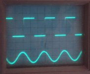
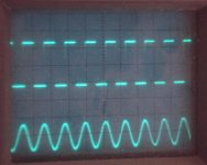
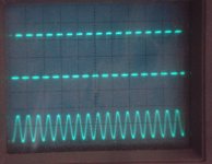
I guess that would make it relatively straightforward to sample the SIN/COS output and derive a 3-phase hall signal from it, as no recalculation of timing should be required, just a "simple" derivation of phases.
Turns out that they must indeed be using a magnet ring with poles equivalent to the rotor magnets, because AFAICT, the peaks of the sine wave remain just ahead of being in sync with the leading edge of the hall square wave, which I show at full throttle below, in three different time settings on teh scope:


I guess that would make it relatively straightforward to sample the SIN/COS output and derive a 3-phase hall signal from it, as no recalculation of timing should be required, just a "simple" derivation of phases.
bigmoose
1 MW
Thanks a ton Amber!! You rock!! That is exactly the info I was searching for. I was after if they synchronized as one sine cycle per physical revolution, or one 2Pi cycle per electrical revolution. Now we know that this manufacturer did it one 2Pi cycle per electrical rev.
Thanks again Amber. Wishing you a most blessed and Happy New Year!!
Thanks again Amber. Wishing you a most blessed and Happy New Year!!
You're welcome; I wonder how many ways there are to do it? I guess...as many as they want, since it could be done with any number of magnetic domains on the encoder ring, right?
I suppose it is easier to do it with a matching number, though.
But I just thought of something: The encoder ring is not on the rotor, but rather on the axle the rotor bolts to, with five bolts. There are 40 magnets (and presumably that many domains on the ring), but how does the controller know they're lined up right? There is no marking on the axle to show it should only go one way. Would it maybe not matter, because there are five bolts and 40 magnets, just that there'd always be 8 magnets to a "side" and thus always line up the same? I dunno...my brain is not up to math right now.
A friend loaned me this optical tach
View attachment 1
to check RPMs with directly, but naturally when I tried to fire up the motor it didnt' spin. Found that three of the hall wires (power and B/G halls) are broken right off the PCB inside the controller.
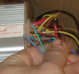
Have to fix that, maybe tonight, and then try the tach.
View attachment 1
to check RPMs with directly, but naturally when I tried to fire up the motor it didnt' spin.

Have to fix that, maybe tonight, and then try the tach.
Well, it's not gonna get RPM tested just yet.
I blew up the controller.
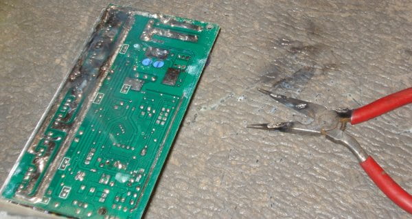
I successfully soldered the wires back in place, (except I put the halls in same color order as phases just to make things easy on me later), reassembled the controller. Hooked it all up and got nothing. DMM showed only 1.4V on the hall power line, but 5V on throttle, so I figure I must've soldered the wire on the wrong pad or something.
Opened up the controller, and couldn't hold the DMM probes steady enough to guarantee not shorting anything out while I probed for another 5V pad, so I just pulled the hall power wire back out of hte case and spliced it into the throttle power line. Still read 5V, so I must've had the wrong pad. Dunno how...it looks like the same one it was on in pics earlier in this thread. :?
Anyway, fixed that, and was setting everything up to test it before putting the case back on, just in case I screwed up something ELSE. Hooked it all up, set the hall wires from motor in same color order as the hall wires from controller since now they shoudl work that way. Held the motor case a bit off the ground while resting the edge of the case on the mat, just so it will not end up twisting and ripping wires.
Powered up, normal current draw per WU, lightly squeezed throttle up and motor spins...then my previously-broken left hand (that has never healed right and has been hurting a lot since late last week) spikes pain and I lose my grip on the motor. I tighten my grip on the throttle without thinking, as I try to catch the motor, and it spins faster and twists the wires out of my hands.
That wouldn't have been a problem, if I hadn't A) not yet put the cover back on the controller, and B) left a pair of needlenose pliers about a foot from where I was working with the motor.
Naturally, the powered up controller PCB landed right on the only metal implement within several feet of it, resulting in an incredible show of sparks that scared every dog out of the room in about a tenth of a second. It took me several seconds to react, cuz I'm tired and my hand was really hurting at that moment, but i got the power disconnected, which stopped the sparking.
Results: Mat, pliers, and controller have interesting burn marks. At least one FET is shorted, cuz the motor is pretty hard to turn.
So...now I have to figure out what exactly is blown, and I have to hope it's only FETs--those I have spares of, and can physically work with. If it's something else, I'm not so sure I can fix it.
Crossposted to the controller thread, too.
http://www.endless-sphere.com/forums/viewtopic.php?p=514878#p514878
I blew up the controller.
I successfully soldered the wires back in place, (except I put the halls in same color order as phases just to make things easy on me later), reassembled the controller. Hooked it all up and got nothing. DMM showed only 1.4V on the hall power line, but 5V on throttle, so I figure I must've soldered the wire on the wrong pad or something.
Opened up the controller, and couldn't hold the DMM probes steady enough to guarantee not shorting anything out while I probed for another 5V pad, so I just pulled the hall power wire back out of hte case and spliced it into the throttle power line. Still read 5V, so I must've had the wrong pad. Dunno how...it looks like the same one it was on in pics earlier in this thread. :?
Anyway, fixed that, and was setting everything up to test it before putting the case back on, just in case I screwed up something ELSE. Hooked it all up, set the hall wires from motor in same color order as the hall wires from controller since now they shoudl work that way. Held the motor case a bit off the ground while resting the edge of the case on the mat, just so it will not end up twisting and ripping wires.
Powered up, normal current draw per WU, lightly squeezed throttle up and motor spins...then my previously-broken left hand (that has never healed right and has been hurting a lot since late last week) spikes pain and I lose my grip on the motor. I tighten my grip on the throttle without thinking, as I try to catch the motor, and it spins faster and twists the wires out of my hands.
That wouldn't have been a problem, if I hadn't A) not yet put the cover back on the controller, and B) left a pair of needlenose pliers about a foot from where I was working with the motor.
Naturally, the powered up controller PCB landed right on the only metal implement within several feet of it, resulting in an incredible show of sparks that scared every dog out of the room in about a tenth of a second. It took me several seconds to react, cuz I'm tired and my hand was really hurting at that moment, but i got the power disconnected, which stopped the sparking.
Results: Mat, pliers, and controller have interesting burn marks. At least one FET is shorted, cuz the motor is pretty hard to turn.
So...now I have to figure out what exactly is blown, and I have to hope it's only FETs--those I have spares of, and can physically work with. If it's something else, I'm not so sure I can fix it.
Crossposted to the controller thread, too.
http://www.endless-sphere.com/forums/viewtopic.php?p=514878#p514878
I wish I had video, it was kinda pretty. 


I may diagnose this tomorrow, i think I'm too tired tonite to deal with it, and my busted hand is throbbing.
I may diagnose this tomorrow, i think I'm too tired tonite to deal with it, and my busted hand is throbbing.
It's fixed...mostly. Runs the motor, but will no longer always start from any position, AND it doesn't work with the same phase / hall combo it used to. :? I'm guessing one of the hall sensor inputs is damaged on the controller MCU, maybe.
Found six FETs blown. All of Phase A (U) and half of Phase B (V). Four were just damaged, so they didn't turn on all the way, with about 500-700ohm RDSon. These might be usable for other test projects, maybe. Two were dead shorts on all three pins, and are scrap.
I didn't have any IRFB3607 FETs so I used some BUZ110s FETs that Solcar had sent me a tube of:
http://www.datasheetcatalog.org/datasheet/infineon/1-buz110s.pdf
They're only 55V instead of 75V, and about a milliohm higher RDSon than the originals, but otherwise similar enough in main specs. Didn't go thru any of the others, like Q or thermal stuff, etc. Can't be picky.
Fortunately the gate drivers weren't toasted. Hooked up the motor back the way it had last worked, with the phases the same as I originally had gotten it working, and the halls color-to-color (since it did work that way just before I blew it up, after I'd resoldered the hall wires in the same color order as the phases on the PCB).
Motor growled but no spin. Putzed around, found a few high-current combos that almost worked, but could find no combo that didnt' occasionally require manual start (just a touch to get it spinning). Found one for each rotational direction like that, and that's all.
I soldered the hall wires from motor to controller, and ensured tight phase connections, and still got the same thing. I dunno what causes it. Scope shows good hall signals, and the same phase signals I had before I blew it up.
I think it kinda sounds rougher than before, too, but not totally sure of that. Same power consumption.
Anyway, my two suspects are:
--hall input to MCU is damaged
--hall inside motor has come loose (they're just glued in place with superglue) and slight position change affected operation.
Neither one makes any sense regarding the change in working phase/hall combo, though.
Anyhow, now I can go back and proceed with RPM tests, after I clean up the repair table.
Back im my fet blowing days  I found it best to change all of a group that any were blown in. Eg on low side blown with 4 on the the low side of that bridge i will change all 4!!! I found even though only one looks blow the other 3 will be damaged!
bigmoose
1 MW
amberwolf said:Naturally, the powered up controller PCB landed right on the only metal implement within several feet of it...
Amber I feel for you bud... Murphy, that blasted, invisible hand of Murphy found you too!! One day we will banish him from our universe!
Yeah, somehow I doubt that's going to be possible. :lol: Teh good news is that even Murphy can go wrong sometimes, so that everything actually goes right! 
Really, though, it was my own stupid fault, because I saw those needlenose there and thought: "If anything goes wrong, I guess I could short out the board or batteries on those things. But I'm holding it steady, and just barely throttling up just for a second to see if it works, so I KNOW that NOTHING can POSSIBLY happen."
Yeah, right.

@Arlo: I usually would change them all out, but I don't want to "waste" FETs on this particular project yet, since I may yet blow the controller up again once I put the thing under a real load. Or once I get the chance to start playing with Burtie's Timing Adjuster 2 that Mdd0127 supplied.
I did the RPM tests, and at the lowest throttle that will keep it moving, it's 42.something RPM. At the fastest, on 10s RC Lipo @40.5V under 1.48A load, it's 348 RPM, measured with that optical tach above shining on a spot at the outer edge of the black rotor that I filed some of the black paint off of to give it a reflective spot to count.
I also did some little videos of the problems it has now that it didn't before, and of the phase waveforms both as voltage and as current, relative to the green hall signal (for a scope trigger).
Startup Problems/etc:
[youtube]fhiuTTS09CI[/youtube]
Voltage waveforms. The Green phase has a little bump in the negative part of the cycle, which is not present in either of the other phases. The Yellow phase has some spikes in it that aren't really visible in the video very well (if at all), which again aren't in either of the other phases. The Blue phase looks like it used to, AFAICT.
[youtube]m9KHmlqMhNA[/youtube]
Current waveforms (measured with a tektronix current probe held against the outer jacket of the phase wires, as they're way too thick to fit in the groove in the probe). Dunno if they're like they were before; I never tested that.
[youtube]Wdd1BqMA6lQ[/youtube]
Does any of that help anyone that's reading see what might be causing the issues, or at least a better guess than mine?
Really, though, it was my own stupid fault, because I saw those needlenose there and thought: "If anything goes wrong, I guess I could short out the board or batteries on those things. But I'm holding it steady, and just barely throttling up just for a second to see if it works, so I KNOW that NOTHING can POSSIBLY happen."
Yeah, right.
@Arlo: I usually would change them all out, but I don't want to "waste" FETs on this particular project yet, since I may yet blow the controller up again once I put the thing under a real load.
I did the RPM tests, and at the lowest throttle that will keep it moving, it's 42.something RPM. At the fastest, on 10s RC Lipo @40.5V under 1.48A load, it's 348 RPM, measured with that optical tach above shining on a spot at the outer edge of the black rotor that I filed some of the black paint off of to give it a reflective spot to count.
I also did some little videos of the problems it has now that it didn't before, and of the phase waveforms both as voltage and as current, relative to the green hall signal (for a scope trigger).
Startup Problems/etc:
[youtube]fhiuTTS09CI[/youtube]
Voltage waveforms. The Green phase has a little bump in the negative part of the cycle, which is not present in either of the other phases. The Yellow phase has some spikes in it that aren't really visible in the video very well (if at all), which again aren't in either of the other phases. The Blue phase looks like it used to, AFAICT.
[youtube]m9KHmlqMhNA[/youtube]
Current waveforms (measured with a tektronix current probe held against the outer jacket of the phase wires, as they're way too thick to fit in the groove in the probe). Dunno if they're like they were before; I never tested that.
[youtube]Wdd1BqMA6lQ[/youtube]
Does any of that help anyone that's reading see what might be causing the issues, or at least a better guess than mine?
Oh, I forgot to note:
Since it is 348RPM at 40.5V, 8.6k/V (RPM per Volt).
So I could get about 480RPM with the pack that's on CrazyBIke2, even under a 40A battery load, which sags to about 56V at full charge. Closer to 53V later, 455RPM. Haven't tested that as the FETs I had to replace the dead ones with are only 55V, and I don't need any more smoke this week. :-(
Similar threads
- Replies
- 3
- Views
- 309
- Replies
- 4
- Views
- 301
- Question
- Replies
- 4
- Views
- 206
- Replies
- 7
- Views
- 215
- Replies
- 12
- Views
- 580

