Problen using two gear shift sensors with BBSHD simultaneously. Anybody tried?

mikel-

1 mW
Joined
Jul 22, 2016
Messages
13
Hello,

My ebike with BBSHD has been working great with 2 brake sensors and 1 gear shift srnsor, but I recently installed 3 speed internal gear hub in addition to 8 speed derailleur/cassette and I have a problem using 2 gear shift sensors together.
I have 2 brake sensors and 2 gear sensors (for 2 different shifters) total. All the sensors work well individually and all the wiring and splitters ae good. I tested each sensor individually with and without splitter cables. The combination of 2 brake sensors and 1 gear sensors works fine (with any of my gear sensors) . But any setup that involves 2 gear sensors (with splitter cable) does not work. It doesn't matter if I have brake sensors connected or not.
I can see green lights on each gear sensor blink when I use the corresponding shifter, but there is no signal to stop the motor. Display usually shows error code when brake or shifter is activated, but not in this case.
If I disconnect either of the 2 gear sensors, the other one starts working perfectly. And I tried all combinations of gear sensors (including 3rd spare one) and I swapped splitter cables and connected sensors to different ports/connectors. No luck.

I am not sure how the output of the sensor works, but probably it pulls up or pulls down the signal wire when active. Maybe there is a pull-up or pull-down resistor in each gear sensor that holds the signal wire at default voltage when sensor is inactive. And when 2 are connected maybe the pull becomes too strong and single sensor cannot bring the voltage to the active level.
This is my best guess.
Has anybody experienced this problem?

Thanks,
Mike
 
I just confirmed my guess :) I opened one of the srnsors and measured the signal on the output wire. Normally it is pulled up to 5v. When any sensor is activated, output voltage goes to 0.
When 2 gear sensors are connected and 1 activated, the output goes to 1.6v, not 0. So it is not pulling the line down sufficiently. I will experiment with adding weak pull-down resistors in parallel to the output to fix the issue.
 
If you can replace the pullup resistors in both units with ones double the value, they should operate as expected. Or remove the resistor completely in one but not the other. Or remove from both and install just one at the controller end.

Pulldown resistors may not give the solution you expect (depends on the controller design), and will cause some extra loading on the 5v supply from the controller *all the time* because there will now always be a complete path from 5v to ground thru the pullup/pulldown series pair(s).
I agree. But I cannot open the sensor case without destroying it. I destroyed the case of my spare sensor.
I hope pull-ups are 5kOhm or more. The current would be in milliamp range with additional pull-down which shouldn't be a problem. But I also suspect there might be issues with that solution (other than load on controller).
 
It depends on the controller's input design, and how it looks for the signal. Doesn't hurt to test. :)

BTW, most of these things (ebrake sensors, gear sensors, etc) use the same general type of open-collector hall sensors that most ebike (and other UVW) motors use (those are equivalent to the Honeywell / Allegro SS41 or SS411). Motors use bipolar latching types, so that it stays at the last triggered state until the magnetic field reverses. The sensors may use a non-latching type that simply turns on (grounds it's output) whenever a sufficiently strong field of either polarity is detected.

But the outputs are still probably open-collector, hence the need for the pullups. (this kind of design is intended to help with noise immunity, since it can be easier to create a clean grounded signal by increasing the current thru the grounded signal line (decreasing the pullup resistance) to "override" the various induced noise signals on the line.

Because the OC halls usually ground down to around 0.8v or so, the controller is probalby looking for anything less than about a volt on the input to call it a valid grounded active signal--you can test that with a potentiometer with 5v and ground on it's outer pins and center pin to the controller input, if you're curious. Note that the controller pullup will affect the circuit, but it will still vary enough to determine the limit if you need to do this or just want to know.
 
Sounds good.
It is interesting that brake sensors seem to have weaker pull-ups than gear sensors. I noticed that combination of 1 gear sensor and 2 brake sensors works most of the time. It misses gear shifting occasionally. But 2 gear sensors (without brake sensors) don't work at all.
 
I don't think hte brake sensors have pullups in them; generally they are extremely simple in design. (none of hte ones I've used do; never had a gearsensor to try out). They depend on the built in pullups in the controller, which is how these systems *should* work, which ensures compatibility between the various kinds of switches used in the various sensors. (some use mechanical switches (SPST momentary), some use OC halls, some use SPST reed switches).

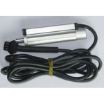
There is a brake sensor called HWBS hidden wire brake sensor
1683085951479.png
that does things a bit differently, more like the gearsensor, and very likely is where the gearsensor design evolved from. I have one here I opened up long ago, but cant' remember how it's output was designed, other than that it was a low-level output when active (grounding), and that it required 5v and ground from the controller to operate, and had an LED to indicate active state. It slipped over the brake cable, replacing a few inches of the cable housing, so it could be used with any bicycle-cable-operated brake.

Right next to the internal cable passthru tube, there was a magnet with a very low tension spring to keep it pushed against the stop. The cable, being steel, would attract the magnet, so the cable moving would move the magnet, pulling enough cable (not much) thru it moved the magnet far enough to activate the hall sensor (reed switch could be used too, but the one I have was a hall) and ground the output. Releasing the lever and letting the cable move back would move the magnet back to the stop and deactivate the output. Pretty sure they had some form of debouncer/etc in there, since it didn't have false triggers from vibration, etc.

Sometimes these failed to release, magnet getting stuck (tapping on them could make them work again for a while, or at least the once).

Might've been improved in the decade or so since I had mine. :)
 
Last edited:
It depends on the controller's input design, and how it looks for the signal. Doesn't hurt to test. :)

BTW, most of these things (ebrake sensors, gear sensors, etc) use the same general type of open-collector hall sensors that most ebike (and other UVW) motors use (those are equivalent to the Honeywell / Allegro SS41 or SS411). Motors use bipolar latching types, so that it stays at the last triggered state until the magnetic field reverses. The sensors may use a non-latching type that simply turns on (grounds it's output) whenever a sufficiently strong field of either polarity is detected.

But the outputs are still probably open-collector, hence the need for the pullups. (this kind of design is intended to help with noise immunity, since it can be easier to create a clean grounded signal by increasing the current thru the grounded signal line (decreasing the pullup resistance) to "override" the various induced noise signals on the line.

Because the OC halls usually ground down to around 0.8v or so, the controller is probalby looking for anything less than about a volt on the input to call it a valid grounded active signal--you can test that with a potentiometer with 5v and ground on it's outer pins and center pin to the controller input, if you're curious. Note that the controller pullup will affect the circuit, but it will still vary enough to determine the limit if you need to do this or just want to know.
Pull-down did not work. :)
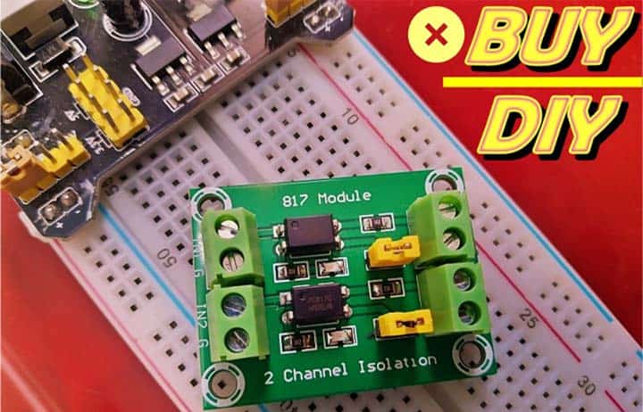
I bought this 2 channel optocoupler module from Amazon and changed the circuit to do what I need.
Diitao PC817 2 Channel Voltage Converter Module Optocoupler Isolation Driving Module 3.6-30V Driver Photoelectric Isolated Module,Suitable for Triode, MOS Tube, Low Power Relay Module (6PCS 2Channel) https://a.co/d/3a4gQl7

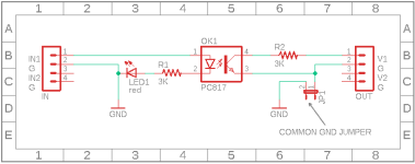
Schematic
Dual-OC-Module-Schematic.png
From here

By default module inputs are active high. So I disconnectrd the ground from the inputs and connected my gear sensor outputs (active low) instead of the ground to separate channels and connected +5v to the positive input of both channels.
I also replaced all (input and output) 3k resistors with 500 Ohm ones and kept existing LEDs. Active input current is about 4mA now which almost saturates IR emitter in the optocoupler and corresponding active output current is 8mA (max possible is 10mA if I reduce input resistor value). Outputs of both channels are connected together and fed into Bafang controller sensor input.
It works. :)

I also bought this solid state relay module.
LM YN 2-Channel Solid State Relay Module High-Low Level Trigger 3A Optocoupler Isolation https://a.co/d/6qlYX3t

It works even better. No need to replace any components, but the module is huge - 2x2 inches. And the box for it would have to be even bigger. The optocoupler module fits into 2x1.2x0.5 inch box.
 
Last edited:
Back
Top