spata
1 W
- Joined
- Jan 26, 2013
- Messages
- 58
I now have some datalogged results of the effects of my outrunner cooling setup and I thought they may be of interest.
The results are from my road legal Honda MT50
The important specs are:
Motor: Turnigy C80100 - 130kv
Controller: Lyen 18FET
Batteries: Lipo 15S 4P (nominal 55.5v - 20ah)
2 stage reduction
Primary: 14T front – 45T rear
Secondary: 14T front – 60T rear
Speed: approx 32-35mph
Weight 75.5kg
The cooling solution I used needed to perform 2 functions: first was obviously keep the motor cool, but equally important was to cover all the rotating parts of the outrunner. I needed the final design to be road legal - pass any safety inspections, and ensure that nothing could get caught by the rotating can.
I also needed to keep the design as slim as possible, this effectively ruled out the 'regular' solution of putting a fan on the motor shaft. I looked for a fan that could work at a high static pressure (needed to get air through the stator) I considered leafblowers and ducted fans, but the sizes and noise were not particularly appealing. Eventually I came across this:
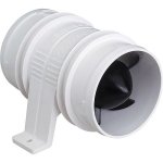
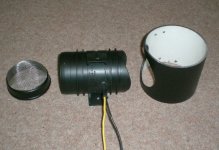
It is an Attwood Turbo 3000 and is used to vent air out of the bilge of boats. It is 3" in diameter - they make a 4" one as well
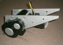
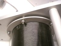
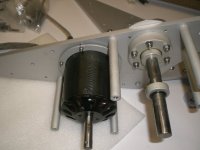
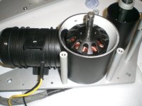
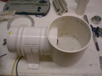
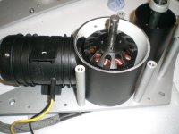
The idea was to surround the C80-100 outrunner in a piece of 110mm diameter plastic waste pipe and connect this to the bilge pump.
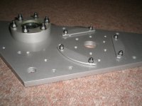
These images should give you the basic idea:
Here are the datalogged results:
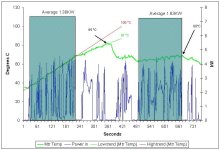
Up to about the 360 second mark the fan cooling was off, the temperature measurement is embedded in the stator and you can see it got up to around 85 degrees C before I chickened out and turned the fan on. I averaged the power in the first green rectangle, it came out at 1.38kW. as you can see the load then dropped but the temperature was still on the way up. I think the eventual temperature, without fan cooling, would likely end up somewhere between the 2 trend lines; ie between 87 - 100 degrees C. Some time after the fan came on the load increases, the second green rectangle (when the cooling was on) shows an average of 1.83kW, temperature however now stays fairly constant peaking at 68 degrees C.
Summary is that the air cooling drops the stator temperature by at least 17 degrees C and my guess is more like 20 degrees C.
It is of course worth remembering that if your motor is uncovered then it will have better cooling in the first place - this was not an option for me as I needed it protected. Unfortunately I do not have any datalogged results for an uncovered motor.
If there is any interest in further details of the construction - air baffles etc, then let me know and I can append the thread.
- Spata
The results are from my road legal Honda MT50
The important specs are:
Motor: Turnigy C80100 - 130kv
Controller: Lyen 18FET
Batteries: Lipo 15S 4P (nominal 55.5v - 20ah)
2 stage reduction
Primary: 14T front – 45T rear
Secondary: 14T front – 60T rear
Speed: approx 32-35mph
Weight 75.5kg
The cooling solution I used needed to perform 2 functions: first was obviously keep the motor cool, but equally important was to cover all the rotating parts of the outrunner. I needed the final design to be road legal - pass any safety inspections, and ensure that nothing could get caught by the rotating can.
I also needed to keep the design as slim as possible, this effectively ruled out the 'regular' solution of putting a fan on the motor shaft. I looked for a fan that could work at a high static pressure (needed to get air through the stator) I considered leafblowers and ducted fans, but the sizes and noise were not particularly appealing. Eventually I came across this:

It is an Attwood Turbo 3000 and is used to vent air out of the bilge of boats. It is 3" in diameter - they make a 4" one as well
The idea was to surround the C80-100 outrunner in a piece of 110mm diameter plastic waste pipe and connect this to the bilge pump.
These images should give you the basic idea:


Here are the datalogged results:

Up to about the 360 second mark the fan cooling was off, the temperature measurement is embedded in the stator and you can see it got up to around 85 degrees C before I chickened out and turned the fan on. I averaged the power in the first green rectangle, it came out at 1.38kW. as you can see the load then dropped but the temperature was still on the way up. I think the eventual temperature, without fan cooling, would likely end up somewhere between the 2 trend lines; ie between 87 - 100 degrees C. Some time after the fan came on the load increases, the second green rectangle (when the cooling was on) shows an average of 1.83kW, temperature however now stays fairly constant peaking at 68 degrees C.
Summary is that the air cooling drops the stator temperature by at least 17 degrees C and my guess is more like 20 degrees C.
It is of course worth remembering that if your motor is uncovered then it will have better cooling in the first place - this was not an option for me as I needed it protected. Unfortunately I do not have any datalogged results for an uncovered motor.
If there is any interest in further details of the construction - air baffles etc, then let me know and I can append the thread.
- Spata


