Re: 5KW 72V Controller 36 #4410 FET's, $108 #4110's $154

I am still waiting for my part from zombiess.... annoyed its taking so long... seems its the only solution to my twitchy throttle

flexy said:
Maybe this 36fet was designed to work with a specific scooter/motorcycle motor, we are all using it in very different setups.
I have the same problem with maintaining a constant speed around 45kph, it will continuously accelerate then coast then accelerate.

I do have a couple of extra shunt wires added just to get up the steep hills. If the current ramp is part of the programming then we have to live with it, but if it is part of the circuit on the board maybe we could bypass it....?
 
The Mighty Volt said:
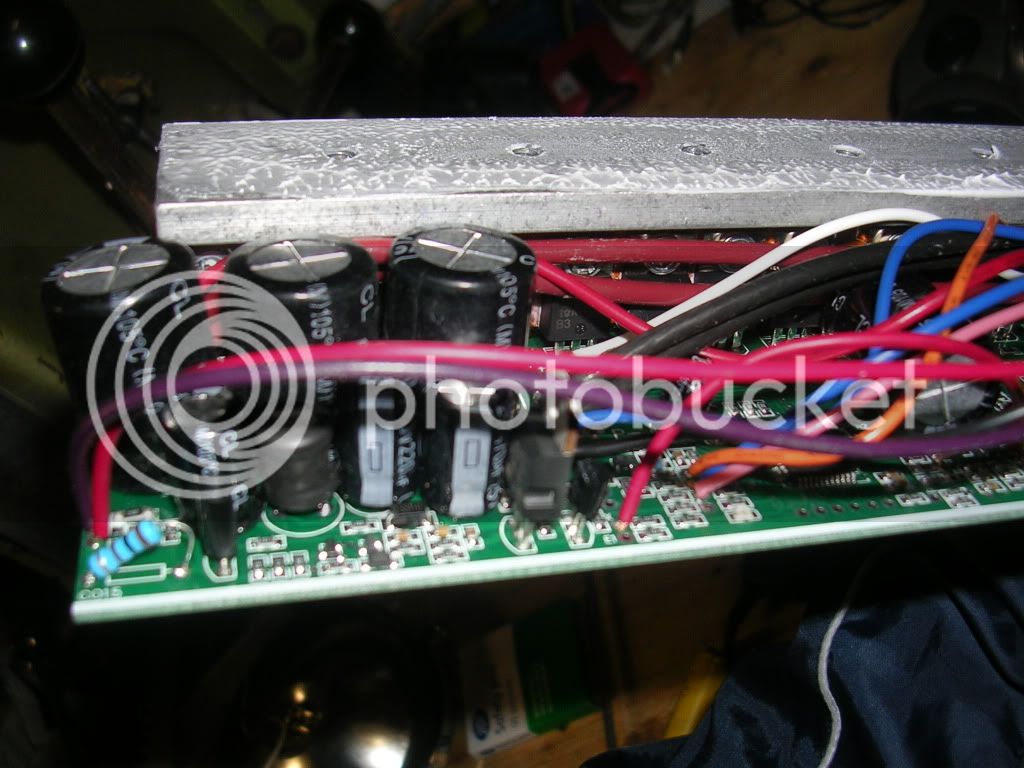
Capacitors of the 24 Mosfet Leo
DSCN5142.jpg

Hi guys I came across this thread researching my greentime 3kw 24fet thought you guys looked like you know more about it than Leo himself who has not responded in days to my questions about

Where my ignition wire is

Plugged in batteries and its automatically on. No wire to put an on off switch seems so bloody ridiculous to ask before buying....

List of all wires wires
red and black are the power wires and the thick y g b are the phase wires....
the rest are thin:
halls
cycle anaylyst

orange black blue = 3 way switch pretty sure
red green black = probably throttle
purple black = backwards
white black = low level brake
yellow alone = high level brake
white white = can be connected to themselves self study
orange orange = can be connected to themselves regen
purple with circle ending to nowhere = battery indicator
pink black = cruising control

This is how it looks from the outside

[youtube]lHgwTz74DRo[/youtube]

Was hoping not to have to undo everything from my second install to the bike.... but looks like I will have to...

Has anyone else got a controller with no ignition wire or switch on the case before? Is there an off the shelf product to create a switch or can some one tell me the location of the ignition wire I need to install? Note this thing is powered up once battery power is connected.

thanks in advance and sorry if this seems irrelevant to the thread here (just going bananas with Leo's lack of response)
 
All the "ignition" wires do is pass battery power to the input of the low-voltage regulator section. So if you have no external wire loop/jumper that can be disconnected for that, then somewhere on the board you'll find a (long-ish, usually) jumper wire from the battery positive input area to another area usually containing the low voltage regulator stuff.

Normally there probably arent' any other jumpers running from one place on the board to another, so if you have only one of those, it's probably the right one. Measure it's voltage at eitehr end, and if it's battery voltage, cut the wire and see if the bike still runs. If not, then that's the one, and you just need to install your switch between the ends of that wire (extending it out of the case if desired).
 
Thanks and sorry Amberwolf I have no background in electronics at all, so I opened pulled off the controller and opened it up to see if anything might match what you are saying but I only see wires going from inside to outside the controller.

12196119_10153619394594845_3013988446490202520_n.jpg


They are Im sorry night time pics, there are more here https://www.facebook.com/media/set/?set=oa.907181486017587&type=1
 
Back
Top