Resistance Soldering Battery Tabs?

Zoot Katz

100 kW
Joined
Jun 21, 2008
Messages
1,543
Location
Vancouver, BC Canada
Do Resistance Soldering methods work for connecting battery tabs?
They're less expensive to buy or construct than a Capacitive Discharge welder and would seem to eliminate the heat transfer problem with regular soldering.
Are they effective? What sort of power would be needed?
 
There's a whole whack of info out there about resistance soldering including instructions for building your own resistance soldering equipment.
From what I'm reading it's the same principal as a soldering gun.
http://www.americanbeautytools.com/site/index.php?req=learn&sub=bulletin&id=31

The plier and tweezer handpieces look to be ideal for battery tab soldering.
http://www.americanbeautytools.com/site/index.php?req=prod&cat=handpieces#10536

So the question remains, has anyone tried it when constructing a battery pack?
Most of the hobby references are about resistance soldering for building brass HO scale stuff.
 
Zoot Katz said:
There's a whole whack of info out there about resistance soldering including instructions for building your own resistance soldering equipment.
From what I'm reading it's the same principal as a soldering gun.
http://www.americanbeautytools.com/site/index.php?req=learn&sub=bulletin&id=31

The plier and tweezer handpieces look to be ideal for battery tab soldering.
http://www.americanbeautytools.com/site/index.php?req=prod&cat=handpieces#10536

So the question remains, has anyone tried it when constructing a battery pack?
Most of the hobby references are about resistance soldering for building brass HO scale stuff.

Nope but I did see a recent instructables http://www.instructables.com/id/DIY_Cold_Heat_soldering_iron on how to make your own...
 
torrent99 said:
Nope but I did see a recent instructables http://www.instructables.com/id/DIY_Col ... ering_iron on how to make your own...
Yep, I've got that one bookmarked.
I've got an ATX power supply and most of the other parts kicking around here. Just gotta come up with a good switch.
Looks like I'm going to have to get busy and see if I can earn myself a fried guinea pig.
 
Zoot Katz said:
Looks like I'm going to have to get busy and see if I can earn myself a fried guinea pig.

Go for it :twisted:

I've never played with resistance soldering. Seems like it should work, but you still need to go fast to prevent heat from melting the cell seals.
 
fechter said:
Zoot Katz said:
Looks like I'm going to have to get busy and see if I can earn myself a fried guinea pig.

Go for it :twisted:

I've never played with resistance soldering. Seems like it should work, but you still need to go fast to prevent heat from melting the cell seals.

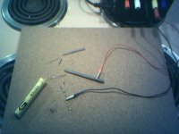
The first test, a proof of concept sorta rig, failed to produce heat.
I grabbed a piece of copper wire with the alligator clip plugged into the neutral jack of the power supply. In the +5V jack I connected a piece of 2mm diameter 6H drafting lead. There was 5.2V between them on the multimeter.
Nuthin' even got warm after 10 seconds.
Time to go back and re-read the instructions.
This guinea pig might get stuffed before it slow roasts.
Edit:
Just toked this over and it fizzed that dude in the Instrucrtables article used a raw power supply from a computer. Mine's been modified per another Instructables article. The ten watt 10 ohm resistor in there is probably what's making the heat instead of the carbon contacts.
Is that a reasonable conclusion?
 
I don't think so. The resistor is just there to provide enough load to keep it running.

Perhaps when you try heating the wire, the supply sees a short and goes into overcurrent shutdown. Typically, the supply will 'hiccup', giving short bursts of current waiting for the overload to be removed. A lower voltage/higher current might work better. You also might have more success if there was enough resistance in the circuit to prevent it from going into shutdown.
 
Thanks for the suggestions.
My thinking was that if the power supply unit saw the work as the load it would turn on and continue to run until the load was removed or the juice cut.
I know from cobbling the unit together, the resistor needed to turn it on got hotter than anything I touched today.
Maybe I can make it extra homework for my EE student neighbour.
 
I did the same test again today except with the multimeter attached to the power supply binding posts. The meter continued to read 5.2V even when the electrode was touching the ground. If the PS is shutting down because of being overloaded, why does it continue to put out 5.2V?

In the mean time, I'm going to fart around with tweezer type handpieces.
I hit on the idea of using a welders soapstone marker for the insulators and carpenters flat pencil lead for the carbon contacts.
They're both readily available and easily shaped materials.
 
Success! (well, sorta)
Same 5 volts test as before except using 0.5mm pencil lead.
It does glow and get hot enough to melt solder it's just too fragile to be of much use and definitely too small for soldering battery tabs.
At 12 volts the 2mm drafting lead glows and melts solder, just not very well and there's a stinky plastic smell coming from the lead. (binders probably)
The 2.16mm X 4.96mm flat carpenter's refill lead works better and doesn't stink but the best results have been with the larger (2.48mm X 5.84mm) carpenters lead boiled and split from its wood.

That's enough progress to encourage me to proceed with this rest of this little project.
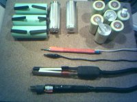
resistance on the range.jpg
stash of stuff.jpg
 
Zoot,

I hope you get this nailed. I've got lots of tabs hoping it works, so they don't have to suffer through my bull in a china shop regular soldering. I'm going to test some of that $2/gm conductive epoxy, as another potential alternative.

Thanks for sharing your progress.

John
 
Thanks John in CR.
Nailing it will have to include some method for regulating the output to control the heat.
Some guys put a light dimmer on the input side but I don't think a computer power supply would like that.
Right now I'm looking at 50W halogen lamp and wondering what its transformer could do. It's already switched for high and low.

Just checked. My fire extinguisher is good until Dec 2012.
 
Scratching through the junk I decided the design needed a bit more R&D (rumination and dope)
A few tokes later a Q&D (quick and dirty) possible solution dropped outta nowhere.
Motor brushes already have a wire attached. Genoursly JB Weld them to bamboo pincer tongs. Hook 'em up. Make smoke.
Costs zip try if you've got any useless brushes laying around. Might need the brush holders too.

I know there's a dead rotary grinder and skill saw deep in another junk box.
Off to scrounge with promises to not plug in anything until tomorrow.
 
Hope i don't interrupt your fun too much, but how about this general idea:

Use the power in the batteries to do the welding or soldering!

Whilst testing if one of the left-over 20A fuses from my Vectux M-BMS project would prevent prolonged shorting of a single 9900mAh NiMH cell, I shorted the cell to itself through one of the fuses.

The tab immediately started to radiate red hot glowing where the cable (30A rated) touched it!

I believe that would have melted any solder if it had happened to be there.


Suggestion:

Place tabs to be joined together with a piece of solder/rosin mix between them, clamp them together somehow, close the circuit for a certain time, like 500 to 1000ms or something like that, automatically open the circuit via a circuit beaker or fuse.

Or am I too far off with this?
 
Mr Mik, Your suggestion sounds good but I don't actually have any batteries yet. Well, none that need soldering. I've never before built a battery pack so this whole exercise is a shot in the dark.

The brushes came out of a dead grinder last night but I resisted testing them until this morning. I attached wires and clamped them to a copper strip in close proximity to each other and turned on the power. Nuthin'. Un clamped one and turned on the power again. The fan spun up and I touched the other brush to the copper. Sparks! This is good. A few more sparks cleaned the schmutz off the brush.
Testing with solder I had a nice shinney puddle in about five seconds. Cool!
This phone pic shows the brushes setting in a blob of JB Weld on the ends of bamboo battens taped to coroplast. The strip in the center is the 0.025" copper test piece.
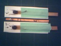
bamboo_brushes.jpg
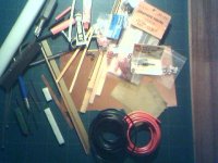
The select pile contained a piece of brass channel stock that has the same inside width as the soapstone refills thickness and almost the same size as the width of the carpenters lead refill.
If that wasn't enough, a square section of the soapstone slips into the split end of a plastic plumbing supply line for sinks. Instant handle.
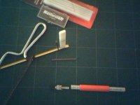
fluke.jpg
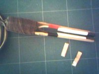
The pieces are held together with thread in this pic.
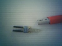
hot_fork.jpg
It's going to be encapsulated in JB Weld. The lead refills will be replaceable by sliding them in between the soap stone and brass.
Placing the battery tabs between the tines and twisting the fork brings them into contact with each other completing the circuit.

It should work. Can clearance might be an issue. We'll see.
 
The bamboo battens with the motor brushes bonded to them were joined together today. A little block of wood forms the fulcrum and handle.
Woven insulation protects the bare leads and spade connector of the motor brushes. . Hockey tape finishes off the handle. The tips of the bamboo can stand to be shaped a bit in order to reduce their width to that of the brushes.

It's hard to see in the crappy phone pic but the two pieces of copper are each sporting a nice coating of solder. The solder melted and flowed in the time it took me to count to three.
tong-test.jpg
Next step is a foot switch and finishing the fork design. Making a single probe out of an old drafting lead holder will be too easy. The stinky 2mm leads just have a coating to reduce dust. It wipes off with acetone.
 
Were I a more patient internet shopper it might have been cheaper to get something ready rolled. . . . but what's the fun of waiting?
This place is almost next door to <ebikes.ca>:http://www.mainelectronics.com/index.htm
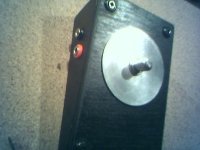
Anyway, the switch is ready, the tongs function, the fork units still need some assembly and testing.
View attachment 1 stomp_switch2.jpg
Now what I need is some trashed batteries on which to experiment. That will probably result in further modification because, without battery building experience or spare batteries on hand, can clearance has remained a unknown factor in all of this exercise. Farting around soldering good batteries without having previously worked out the techniques would probably be unpleasant.
 
hmmm, thought I'd already posted this. . . Oh well, here's a rough summation:

Zev gave me some batteries from the <ebikes.ca> recycle bin.
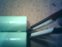
Can clearance will be an issue.
The tongs and fork hand pieces require modification to work as envisioned though they might, in practice, suggest other techniques that I'd ignorantly not considered.
The drafting lead holder only needed a ring terminal between the collet jaws and collar to make contact. Might be handy in limited applications.
A face shield is the next purchase before I plug in and start poking at batteries.
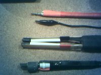
ready1.jpg
handpieces.jpg

It seems I'm almost ready to answer the question initiating this thread.
 
Zoot Katz said:
A face shield is the next purchase before I plug in and start poking at batteries.

Good idea, and keep a camera rolling just in case... :wink:
 
Can it really be this easy?
Here's two scraps of fluxed nickel connector strips with a ~1.5cm piece of 1mm rosin core solder between them. Three seconds later they couldn't be separated. It looks it was almost too much solder (bad).
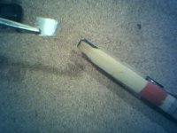
ready2.jpg
So the question is, can tabbed batteries be joined as shown? It would certainly be less questionable if the tabs had been spot welded 180° apart.
Would it be acceptable practice to solder the tabs together where they're joined with glue in this pic:ready3.jpg
. . . and then fold them back over the flat end of the battery where the excess would be trimmed off?ready4.jpg
Anyway, if all tabbed cells can be assembled this easily, and 180° bends in nickel strip is okay, then it's starting to look like a sweet method for soldering them together.
 
This whole exercise began as a search for miniature open-end wrenches. Then it went lateral. MicroMark specialises in tools for hobbyists so I downloaded their catalogue and became intrigued by the resistance soldering outfit they sell.

Asking around didn't provide many answers as most people hadn't even heard of resistance soldering let alone tried it. They grasp the principal quickly enough. Hek, even I "got it" so you know it's not difficult.

I stumbled around getting the equipment cobbled up and working without ever having built or dissected a battery pack yet I feel the method can be pronounced sound. Confirmation will have to wait until I buy enough batteries to make a pack. I don't need an extra pack right now.

My remaining question was answered today when I saw these images.
newbattpack.jpg

newbattery.jpg
LiPoPack_6090fb60.jpg
LiPoPack_51daab37.jpg


The stick configuration NiCd pack shows the joined tabs sticking past the sides of the cans where they're insulated and folded over. The LiPo pouches' tabs are joined and folded back over one of the tabs where they're hot-glued. My tongs would be ideal in either of these applications.
I figure that folding the tabs back over the top and bottom of the cans would be acceptable and just produce a pack that was kinda lumpy.

Just to keep my juices flowing I'm going to hack at making a jig so that nickel tabs can be soldered onto buttons and bottoms of un tabbed cells, or better yet, the previously tabbed cells salvaged from tool packs.
Something like the "Dean's Speed Jig" with the clamping mechanism for the nickel strips providing the ground and a ¼" copper clad gouging rod pressing down on the cell ends.
SPEED-JEG-re-tuch.jpg
 
I've not yet built any battery packs but this weekend I got to use my resistance soldering rig in a different application at which it possibly excels.

Coffee Luke wanted to clean up the wiring on his ghetto Ratt Werx ride. His love for the Rainbow Family was evident in the multi-coloured rattz nest that passed for a. . .uhhh, wiring harness?

Making end to end, butt and inline splices with the tongs was a breeze. I was able to work in tight spaces in order to solder free dangling wires.

The 350 Watt power supply choked on 10 AWG wire. It can handle two at a time with a rest period for cooling between successive joints.

The bamboo tongs have held up remarkably well. Instead of wiping my tip on a damp sponge to clean it, I occasionally have to wipe the tongs to cool the ends. Some emery paper cleans the contact surfaces when they get varnished with rosin.

Perhaps because of the larger surface or better material or better internal electrical contact, the motor brushes mounted in the tongs works best of any of the other hand pieces I built.

Oh yeah, the lights didn't work when I was finished soldering and taping all the joints in the new wires. No panic. The next day revealed the switch grounding on the frame. Not my problem.
 
Back
Top