
It's alive! 
You are using an out of date browser. It may not display this or other websites correctly.
You should upgrade or use an alternative browser.
You should upgrade or use an alternative browser.
Rickys High Power Flexable motor controller
- Thread starter Ricky_nz
- Start date
Kingfish
100 MW
Hey Ricky
I’ve been a happy fly-on-the-wall admiring your progress with enthusiasm (subscribed from the beginning)! When you suggest moving the frequency to 40KHz, target 44KHz instead; that’s twice above (perfect) human level and coincidentally the rate at which early CD-sampling used. It seems to me that frequency generators of that range would be very common. Just my ½ watt. I’ll go away now and back to observing from the wall.
Great work! KF 8)
8)Ricky_nz said:I have split my main state machine so its easier to write tests that can be used for calibration etc and to separate out the normal operating mode........... This also makes it easier to write alternative state machines for special applications.
")
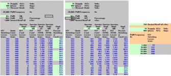
I would not move the pwm just based on sound.... This chart shows losses go up by a ratio the same as the PWM frequency eg. 40000 hz will have double the switching losses compared to 20000 hz.Kingfish said:Hey Ricky
I’ve been a happy fly-on-the-wall admiring your progress with enthusiasm (subscribed from the beginning)! When you suggest moving the frequency to 40KHz, target 44KHz instead; that’s twice above (perfect) human level and coincidentally the rate at which early CD-sampling used. It seems to me that frequency generators of that range would be very common. Just my ½ watt. I’ll go away now and back to observing from the wall.
Great work! KF 8)
Attachments
Alan B
100 GW
Dynamic FET losses will roughly double, but the effective inductive reactance will also double and the capacitance ripple current will go down by half so if you have good FETs and drivers it is not clear what the best frequency is without deeper analysis.
Ricky_nz
10 kW
I can pretty much choose any frequency I want. because I have 120MHz divided in in a 32 bit counter to generate the PWM signals so it will be limited byt other apects of the design. It all starts from a 12MHz crystal. These modern micros make it so easy with internal PLLsKingfish said:I’ve been a happy fly-on-the-wall admiring your progress with enthusiasm (subscribed from the beginning)! When you suggest moving the frequency to 40KHz, target 44KHz instead; that’s twice above (perfect) human level and coincidentally the rate at which early CD-sampling used. It seems to me that frequency generators of that range would be very common. Just my ½ watt. I’ll go away now and back to observing from the wall.
.I'm guessing my final frequency will be lower than 44KHz although I have run the motor at near that speed but these is still a few variables that may come into play. It was more of a test to prove how much headroom was available.
I will have to see how much bigger the code gets in the critical high speed section and also look at switching losses in more detail.
For some motors different frequencies might help so it is configurable.
The higher the frequency the more samples and the cleaner the sinewave output and better control response which is always good but unfortunatly as arlo mentioned it brings about higher switching losses.
As with any design that is always a set of tradeoffs. I think my origional 12KHz is pretty much a minimum for control at 1KHz output so probably arround 20KHz might be where it ends up but I will have to check the switching loses etc.
Ricky_nz
10 kW
This is what makes some of this power electronics design tricky is all the design trade offs and the fact that the component manufacturers can't produce 'ideal' components :lol:Alan B said:Dynamic FET losses will roughly double, but the effective inductive reactance will also double and the capacitance ripple current will go down by half so if you have good FETs and drivers it is not clear what the best frequency is without deeper analysis.
I think 12k - 44khz would be a good range for most motors. The real test will be how much heating you get at the higher frequency assuming everything else works.
Ricky_nz
10 kW
Busy few weeks
The first few working weeks of the year have been rather hectic.
This week had urgent software changes to get working at work and jury service mixed in.
The first time I had done jury service and never once got past the first section. That was 3 mornings I could have been working on the urgent software at work but instead i had to waste going into the court to not have my name drawn .
.
Massively inefficient the way they do it here. Get 90 people in and draw 35 each who are then used to select the 12 jurors for a case. Out of the 3 cases they had scheduled for the week one was postponed due to a critical witness not turning up. They wouldn't let the 35 not selected go until the judge was happy with the first 35. Inconveniently they would let us out about 5 minutes after the bus home had left and the next wasn't due for an hour .
.
Working half days when the problem I was working on needed a bit longer in one session wasn't a good combination. Anyway got the software working to a state suitable for the hardware boys to do some testing last thing Friday.
Still some tidying up to do but it does the job on a small 3∅ setup at my desk. The HW guys will test probably do their first tests on a baby machine of around a few hundred KVA.
Back to the motor controller finally
I have added a zero sequence injection block to my code. This block moves the common mode voltage around so that the motor sees more voltage across its windings.
I had it written a while ago but hadn't hooked it up or tested it and had forgotten about it but its now added I now have more voltage available to the motor for the same battery voltage.
I have got the hall effect sensor test/calibrate state machine working reasonably well and storing the correct values on the sdcard.
The values are correctly loaded through my parameter system that is now quite stable.
The controller decides which normal operation state machine to used based on another parameter on the sd card.
I need to hook up the throttle input block but the normal mode expects a torque input and an enable as parameters enabling me to test it without the throttle.
This weekend I think I will add output voltage limiting to prevent loss of control by requesting excessive current at high RPM etc.
This is necessary because requesting currents that cannot be achieved in the motor due to back emf and the current battery voltage can cause the current control loops to go unstable and that is a 'bad thing'.
The first few working weeks of the year have been rather hectic.
This week had urgent software changes to get working at work and jury service mixed in.
The first time I had done jury service and never once got past the first section. That was 3 mornings I could have been working on the urgent software at work but instead i had to waste going into the court to not have my name drawn
Massively inefficient the way they do it here. Get 90 people in and draw 35 each who are then used to select the 12 jurors for a case. Out of the 3 cases they had scheduled for the week one was postponed due to a critical witness not turning up. They wouldn't let the 35 not selected go until the judge was happy with the first 35. Inconveniently they would let us out about 5 minutes after the bus home had left and the next wasn't due for an hour
Working half days when the problem I was working on needed a bit longer in one session wasn't a good combination. Anyway got the software working to a state suitable for the hardware boys to do some testing last thing Friday
.Still some tidying up to do but it does the job on a small 3∅ setup at my desk. The HW guys will test probably do their first tests on a baby machine of around a few hundred KVA.
Back to the motor controller finally
I have added a zero sequence injection block to my code. This block moves the common mode voltage around so that the motor sees more voltage across its windings.
I had it written a while ago but hadn't hooked it up or tested it and had forgotten about it but its now added I now have more voltage available to the motor for the same battery voltage.
I have got the hall effect sensor test/calibrate state machine working reasonably well and storing the correct values on the sdcard.
The values are correctly loaded through my parameter system that is now quite stable.
The controller decides which normal operation state machine to used based on another parameter on the sd card.
I need to hook up the throttle input block but the normal mode expects a torque input and an enable as parameters enabling me to test it without the throttle.
This weekend I think I will add output voltage limiting to prevent loss of control by requesting excessive current at high RPM etc.
This is necessary because requesting currents that cannot be achieved in the motor due to back emf and the current battery voltage can cause the current control loops to go unstable and that is a 'bad thing'.
Ricky_nz
10 kW
Just pulled the scope image of the zero sequence injection in action off my flash drive.
The yellow trace is the input voltage to the block for U phase and the blue is the output voltage of the block for U phase.
This is done on all 3 phases in such a way as to get more voltage swing for the motor using sine waves.
The motor still sees full un-distorted sine waves but at a higher voltage than could be achieved without this code.
View attachment zero_seq_injection.BMP
I was just thinking about that yesterday!!! Man thats cool i wonder how far you can push it?Ricky_nz said:Just pulled the scope image of the zero sequence injection in action off my flash drive.
The yellow trace is the input voltage to the block for U phase and the blue is the output voltage of the block for U phase.
This is done on all 3 phases in such a way as to get more voltage swing for the motor using sine waves.
The motor still sees full un-distorted sine waves but at a higher voltage than could be achieved without this code.
Ricky_nz
10 kW
From memory I think its about 15% peak voltage increase. It relies on the fact of when one sine wave is at max the other two aren'tArlo1 said:I was just thinking about that yesterday!!! Man thats cool i wonder how far you can push it?Ricky_nz said:Just pulled the scope image of the zero sequence injection in action off my flash drive.
The yellow trace is the input voltage to the block for U phase and the blue is the output voltage of the block for U phase.
This is done on all 3 phases in such a way as to get more voltage swing for the motor using sine waves.
The motor still sees full un-distorted sine waves but at a higher voltage than could be achieved without this code.
There is an absolute limit to maintain clean sine waves. Basically the output stage can only generate a maximum voltage between two phases so this allows us to use all of it by moving the virtual neutral in the motor arround.
The increase should be the difference between the peak-peak values of my two scope traces. It is a significant voltage so well worth doing
Nuts&Volts
100 W
This essentially means you can get up to 15% more power out of a specific motor, controller and battery voltage setup (that is voltage limited), because you can increase base speed roughly 15%. Or in electrical terms you you can combat the BEMF 15% further out and thus send peak phase current 15% more.
What percentage of battery voltage can you now send the motor? I have seen that battery voltage can be about radical 2 (1.41) higher than motor voltage line to line.
Hopefully everything in my head is somewhat right..
What percentage of battery voltage can you now send the motor? I have seen that battery voltage can be about radical 2 (1.41) higher than motor voltage line to line.
Hopefully everything in my head is somewhat right..
Ricky_nz
10 kW
I haven't had my morning coffee yet so ....Nuts&Volts said:This essentially means you can get up to 15% more power out of a specific motor, controller and battery voltage setup (that is voltage limited), because you can increase base speed roughly 15%. Or in electrical terms you you can combat the BEMF 15% further out and thus send peak phase current 15% more.
What percentage of battery voltage can you now send the motor? I have seen that battery voltage can be about radical 2 (1.41) higher than motor voltage line to line.
Hopefully everything in my head is somewhat right..
You are on the right track with the √2 RMS to peak conversion. If you just generate sinewaves with a FET bridge you can only get a peak of the DC bus voltage so the RMS is 1/√2 = 0.707 of the DC bus voltage. This code I added moves the peak above the DC Bus voltage.
I just measured my controller running near full speed on a low DC Bus. The meter isn't a true RMS type but the wavefore is essentially sine wave. The numbers seem to make sense. I would have to borrow a nice meter with true RMS and input filters to get better results on the phase outputs. I really need to buy an isolated differential probe for my oscilloscope.
With the DC Bus at 12.2V.
I measured about 9.5V RMS phase to phase.
The peak is √2 * 9.5V = 13.4V phase to phase or 26.8V pk-pk.
Without the offset injection code the peak voltage would be the DC bus voltage (12.2V),
Ricky_nz
10 kW
I spent half the morning trying to figure out why I had a blip of output current occurring about every 300ms .
I first head the blip with the motor stopped.
I initially thought it was a control loop going wild so I hooked my scope up so i can see the internal value measured by the ADC and the blip is there.
I disabled the PWM output and it was still there so I got suspicious that my ADC wasn't being read correctly.
Eventually I realised that I had neglected to update the ADC sampling point on change of PWM frequency when I added the selectable PWM frequency code .
.
That prompted me to finally setup Bugzilla on my server.
I have been getting sick of making notes in various places when I spotted a bug or something I need to do with the controller software.
I use it at work so I figured I might as well use it at home. It makes keeping track of bugs and planned features easy. Its way overkill but simple enough to setup and use.
Now I need to spend a bit of time loading in things I know I need to finish and features to add etc.
Shouldn't take too long but it will ensure I don't forget anything. FIXMEs in the code only go so far.
.I first head the blip with the motor stopped.
I initially thought it was a control loop going wild so I hooked my scope up so i can see the internal value measured by the ADC and the blip is there.
I disabled the PWM output and it was still there so I got suspicious that my ADC wasn't being read correctly.
Eventually I realised that I had neglected to update the ADC sampling point on change of PWM frequency when I added the selectable PWM frequency code
That prompted me to finally setup Bugzilla on my server.
I have been getting sick of making notes in various places when I spotted a bug or something I need to do with the controller software.
I use it at work so I figured I might as well use it at home. It makes keeping track of bugs and planned features easy. Its way overkill but simple enough to setup and use.
Now I need to spend a bit of time loading in things I know I need to finish and features to add etc.
Shouldn't take too long but it will ensure I don't forget anything. FIXMEs in the code only go so far.
deVries
100 kW
Bumping for any updates... it's been sooo long... (by Ricky_nz » Sat Jan 28, 2012 6:54 pm ) been dreaming about your controller since you started this thread... 8)
Ricky_nz
10 kW
HI All,
Just has a PM from deVries that reminded my I hadn't really been on the sphere for quite a while... The email on PM feature is really handy.
I just got busy with house maintenance and visitors chewing up my spare time.
Now that the weather is getting cooler and its darker earlier I should be able to find more time to work on my controller.
Now I've paid for my kitchen changes and a few other things I can spend on my hobbies again so I'm sending off an order to digikey for some more parts next week so I can make a minor repair to my first board and also get the parts to build up a second controller. I will put it in a box so I can try it in sensored mode on a bike while I get the sensorless stuff sorted.
I haven't had time to work on the software but hopefully I'll get back into that shortly.
I just had to make use of the good weather for general maintenance on my house. Also removing TV aerials and replacing one.
With analogue switch off coming the VHF antenna is gone and the combiner and corroded UHF aerial are also gone. I replaced the UHF with a slightly higher gain one and put up new coax and the original stuff was full of water (I was on the place when I brought it) The new stuff won't get water in it!
While I was on the roof a bit of fine tweaking and my 70cm satellite dish receives NZ freeview and also the Aussie SBS channels both with 0 bit errors! Kind of strange sitting on the roof with a laptop :lol:.
I had to get my mythtv box nice and reliable as none of my TV's have DVBT tuners and I don't have a set top box so when analgue is gone I have no backup for the mythtv setup. Mind you I wouldn't want to watch TV without the mythtv box :lol:.
I have had a new set of Lipo here to build an 16S2P pack sitting here and after a couple of cycles I had left it to sit for a month and there is no significant self discharge imbalance between the cells so I think its good enough so I will probably build up a pack and then I will take the two year old pack off the bike and use it for controller development. Just need to change the caps on a e-crazyman controller as 67V is probably a bit too high for the 48V one :lol:. You heard right my little 300W headline/cyclone/elation is in line for 67V.
If I order some smaller CT's than the 200A ones I have on the first controller I built I could probably run my controller sensored in the place of the ecrazyman which is probably a good idea. I think the 50A CTs should provide sufficient resolution that I can control the current in the headline motor so if they are In stock I'll order a couple. I also need to get a couple of rain proof boxes to put my controllers in. The more I think about it I think I will build up one controller for the GM 1000W hub with 200A CTs and one for the headline with 50A ct's and only 6 FETS fitted.. For the headline it probably won't even need a heatsink :lol:. I figure if i tried to even put 35ARMS (50A peak) in the cyclone windings they might cook hence the 50A to handle the peak. If i can't get 50s Ill get 100A CT's the 200's just don't really give enough resolution for small motors.
Anyway I'll try and keep the updates more regular as I get back into the motor controller project.
Ricky_nz
10 kW
Finally ordered the parts I needed to continue from Digikey this morning so hopefully I can start making progress again.
Its great timing as ordering the parts Saturday morning NZ time as it has them out of Digikey before their weekend starts. I already have valid tracking data showing they are moving through the US. Hopefully I'll have the parts before next weekend provided I don't have issues with customs.
As often the case Murphy struck and I left a couple of parts off.
Why is it I always think of something I should have ordered just after finally confirming the order
Seems to be related that the problem of not spotting spelling errors until the print button is pressed :lol:
It was just a couple of hall sensors and some mini fit connectors I didn't order which luckily are available and in stock locally from rs components for a slightly higher price.
Its great timing as ordering the parts Saturday morning NZ time as it has them out of Digikey before their weekend starts
. I already have valid tracking data showing they are moving through the US. Hopefully I'll have the parts before next weekend provided I don't have issues with customs.As often the case Murphy struck and I left a couple of parts off.
Why is it I always think of something I should have ordered just after finally confirming the order
Seems to be related that the problem of not spotting spelling errors until the print button is pressed :lol:
It was just a couple of hall sensors and some mini fit connectors I didn't order which luckily are available and in stock locally from rs components for a slightly higher price
.Ricky_nz
10 kW
small update
On Friday I got my Parts from Digikey and also another package from hobby king so I can start playing with the hardware again.
I pulled out a partially assembled power board I had set aside waiting for parts and completed assembling the power supply section and decided to test it but it wouldn't power up. The output was 0.2V!
It wasn't drawing excessive current.
The under voltage lockout threshold was crossed and the chip on chip regulator was becoming active and providing the correct voltage.
The bottom FET had very short gate pulses.
All the SMD resistors were correct and I was certain the caps are the correct value as I double checked them as I assembled it.
I started probing around a bit more and eventually found the soft start pin stuck at 0V!
I measured a hard short to 0V but I could not see a short with a magnifying glass and couldn't wick anything out from behind the pin on the converter chip.
I finally decided to stop wasting time and just pull the chip So I cut the legs off the NZ$9 chip and then heated the ground plane vias below the chips ground pad and removed it and in the process cleared the short. What I believe happened was I got the chip slightly askew and not flat enough to the board so a small blob of solder managed to flow between the ground and and the back of the pin when I soldered the ground and due the the thermal mass of the ground I couldn't melt the bridge from the pin side!
Heres a photo of the bottom side of the replacement chip. The big pad being ground and the pin spacing center - center = 0.5mm!

I guess I just need to be more careful mounting these chips as there isn't much room for error. Also I should probably feed a minimum amount of solder through the vias to reduce the chance of shorts also.
At least I know that my board provides good heatsinking of the chip as I had to dump my 70W iron into the ground for a significant amount of time before I could free the chip.
I have got a diecast box to put the second controller in and if It works out alight I'll buy another of the same type and build up a third controller.
Not sure how I am going to cut rectangular holes in a diecst box.
In the past I've done it with a bunch of holes and a file but that is kind of painfully slow. Maybe I should buy a dremal or similar rotary tool to save some time. I'm sure that would allow me to cut holes in the wrong places quicker :lol:
EDIT: After a coffee I decided to solder on the new chip and power it up and it fired right up.
Now I need to build up the gate drive section but that can wait till tomorrow.... err um tonight... 30 mins past midnight here oops.
On Friday I got my Parts from Digikey and also another package from hobby king so I can start playing with the hardware again
.I pulled out a partially assembled power board I had set aside waiting for parts and completed assembling the power supply section and decided to test it but it wouldn't power up. The output was 0.2V!
It wasn't drawing excessive current.
The under voltage lockout threshold was crossed and the chip on chip regulator was becoming active and providing the correct voltage.
The bottom FET had very short gate pulses.
All the SMD resistors were correct and I was certain the caps are the correct value as I double checked them as I assembled it.
I started probing around a bit more and eventually found the soft start pin stuck at 0V!
I measured a hard short to 0V but I could not see a short with a magnifying glass and couldn't wick anything out from behind the pin on the converter chip.
I finally decided to stop wasting time and just pull the chip So I cut the legs off the NZ$9 chip
Heres a photo of the bottom side of the replacement chip. The big pad being ground and the pin spacing center - center = 0.5mm!
I guess I just need to be more careful mounting these chips as there isn't much room for error. Also I should probably feed a minimum amount of solder through the vias to reduce the chance of shorts also.
At least I know that my board provides good heatsinking of the chip as I had to dump my 70W iron into the ground for a significant amount of time before I could free the chip.
I have got a diecast box to put the second controller in and if It works out alight I'll buy another of the same type and build up a third controller.
Not sure how I am going to cut rectangular holes in a diecst box.
In the past I've done it with a bunch of holes and a file but that is kind of painfully slow. Maybe I should buy a dremal or similar rotary tool to save some time. I'm sure that would allow me to cut holes in the wrong places quicker :lol:
EDIT: After a coffee I decided to solder on the new chip and power it up and it fired right up
.Now I need to build up the gate drive section but that can wait till tomorrow.... err um tonight... 30 mins past midnight here oops.
John in CR
100 TW
Arlo1 said:h0tr0d you are to impatient. There is many of us working on bad ass controllers but if you want it any faster you need to build your own.
That or figure out how to get the most out of cheapies. I'm getting 15-25kw peaks at well under 1.5cents/watt. 8)
Ricky_nz
10 kW
No sorry,h0tr0d said:Any updates on this?
Sales thread?
Not enough progress in 2012.
To much house maintenance (did i mention painting roofs sucks). The roof is galvanised iron (steel) and the galvanising was getting thing (40 years old) so I had to kill some rust and then two coats of good primer (oil based one as the water based ones are no good on old roofing) and then a couple of coats of water based top coat. Also replaced a heap of old lead head nails with roofing screws.
All done now and looks good and didn't cost too much thanks to my dads trade account at local paint store
.I also had to spend some time making sure I have a second working bike as my place of work is moving to a new building further away so I wanted a backup. now i have multiple batteries etc so I can mess with one bike and still have the other working etc
Enough with the excuses :lol:
I'm just about to start getting back into it seriously now the Christmas visitors have gone.
I'll try and do some more updates when I make some progress.
I think I have figured out why I managed to kill a couple of power supply chips LM5116 ( killed another one handling the board while powered up recently). I have located a via on the board that is a low voltage point of the converter chip that is way too close to a +100V track. I guess I missed a clearance rule in the PCB layout
I have some more control code changes that after a bit more fiddling in the simulator I will transfer to code.
h0tr0d
1 kW
- Joined
- Apr 28, 2012
- Messages
- 460
John in CR said:Arlo1 said:h0tr0d you are to impatient. There is many of us working on bad ass controllers but if you want it any faster you need to build your own.
That or figure out how to get the most out of cheapies. I'm getting 15-25kw peaks at well under 1.5cents/watt. 8)
Nahhh... I'm just looking for a cost effective solution. The needed learning curve regarding controllers is long and steep. If I've got to go in that direction, I'll probably abandon this project.
There's many people here that "almost" have a working controller, or basis, all didn't quite make it. This is very unfortunate I would say.
For them, could make good money (and pay other people to fix their roof, ex. ) and help this community and entire EV revolution.
Since Jeremy's "lobo" controller could, in theory, go up to 100khz PWM, and phase current control, I'll investigate that...
Happy New year to all, may all your projects succeed!
Lebowski
10 MW
my controller works fine (I think :wink: ) just got no big motor / battery / vehicle combo to try it on
But I don't believe there's (big) money to be made from a good controller
Batteries and motors, that's where the money is, controllers are just seen as the
bit you need in the middle to get it working. Like with cars, the money is in the
gas (not in the cars anymore, ask GM), not in building the carburetor.
Similar threads
- Replies
- 0
- Views
- 142
- Replies
- 24
- Views
- 2,041
- Replies
- 11
- Views
- 1,887
- Replies
- 63
- Views
- 7,447
- Replies
- 20
- Views
- 3,008