
I am not an expert, in fact when it comes to bikes, up until a couple of weeks ago I hadn't ridden a bike for 40+ years, let alone worked on one. I am however reasonably competent at electronics and DIY and a have a go hero when it comes to repairing things. As I couldn't find out much about this motor when searching I thought I would create this thread for others.
I recently acquired an Apollo Phaze eBike, that was only fours years old but the e part was not working, after checking the obvious things like connectors and cables I discovered the cable was damaged where it goes into the hub. I managed to repair the broken wires and the bike has been working fine while I waited for a new cable and the time to do it.

The first job is to remove all nuts and washers, making a note of the order. As there are no screws holding the motor together you will need a special tool to open it. You can probably buy a proper tool or you can make something yourself such as this...

The hole is 13mm and the bolts are M6 at about 42mm centers. It would be better to use something a little bigger and file or grind them to make them a better fit, but this did the job for me. NOTE. Unscrew the opposite side to the cable and it is a LEFT HAND thread.
Once the cover is removed you will see the gears...

The gears can be pulled off and I put mine in a plastic bag to keep them clean and also prevent the grease from making a mess. Note. Don't loose the washer.

Also watch out for the detachable locking pin...

Once the gears are off you should be able to pull the motor out...


After removing the yellow isolation/cover plate we can see how things are laid out.

Simply slide back the sheathing and unsolder the old wires.

The PCB will need to be removed to access the blue winding and also make it easier to connect the new hall sensor wires. I unsoldered the hall sensors as it looked like they are glued in place.

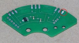
I then removed the sensor wires and cleaned up the PCB... Note. the hall sensor traces are quite delicate, you can see one of mine is starting to lift.

Now you can unsolder the other winding connections making a careful note of what goes where...

Once all wires are unsoldered the old cable can be pulled out, Note. It is easier if you pull the individual wires out one at a time.

We are now ready for the new cable...

I bought a cheap extension cable from China and cut the female end off, slid over a piece of heatshrink with adhesive and a new spring. I also left the cap on to protect the pins. Note. So be safe, I also checked the pin outs of both cables to ensure the colors matched.

Getting the new cable through was much easier than I thought it would be and I left about 20cm from the spindle to the plug tip.

Take your time to ensure you don't damage any wires and strip the outer sheathing back...

Cut the wires to length and solder them as required. Replace the PCB, not forgetting the white insulation piece underneath it...

Fit the yellow plate and we are ready to test...

After a successful test I wasn't completely happy with the way the wires were sitting and I also wasn't sure which way round the yellow plate went. I moved some of the wires, flipped the plate round after looking at my earlier photos and added some fresh thread lock to the 4 screws and this is the finished motor...

Now it's just a case of reversing the steps to put it all back together, not forgetting the locking pin or washer and mount it back on the bike.
I recently acquired an Apollo Phaze eBike, that was only fours years old but the e part was not working, after checking the obvious things like connectors and cables I discovered the cable was damaged where it goes into the hub. I managed to repair the broken wires and the bike has been working fine while I waited for a new cable and the time to do it.
The first job is to remove all nuts and washers, making a note of the order. As there are no screws holding the motor together you will need a special tool to open it. You can probably buy a proper tool or you can make something yourself such as this...
The hole is 13mm and the bolts are M6 at about 42mm centers. It would be better to use something a little bigger and file or grind them to make them a better fit, but this did the job for me. NOTE. Unscrew the opposite side to the cable and it is a LEFT HAND thread.
Once the cover is removed you will see the gears...
The gears can be pulled off and I put mine in a plastic bag to keep them clean and also prevent the grease from making a mess. Note. Don't loose the washer.
Also watch out for the detachable locking pin...
Once the gears are off you should be able to pull the motor out...
After removing the yellow isolation/cover plate we can see how things are laid out.
Simply slide back the sheathing and unsolder the old wires.
The PCB will need to be removed to access the blue winding and also make it easier to connect the new hall sensor wires. I unsoldered the hall sensors as it looked like they are glued in place.
I then removed the sensor wires and cleaned up the PCB... Note. the hall sensor traces are quite delicate, you can see one of mine is starting to lift.
Now you can unsolder the other winding connections making a careful note of what goes where...
Once all wires are unsoldered the old cable can be pulled out, Note. It is easier if you pull the individual wires out one at a time.
We are now ready for the new cable...
I bought a cheap extension cable from China and cut the female end off, slid over a piece of heatshrink with adhesive and a new spring. I also left the cap on to protect the pins. Note. So be safe, I also checked the pin outs of both cables to ensure the colors matched.
Getting the new cable through was much easier than I thought it would be and I left about 20cm from the spindle to the plug tip.
Take your time to ensure you don't damage any wires and strip the outer sheathing back...
Cut the wires to length and solder them as required. Replace the PCB, not forgetting the white insulation piece underneath it...
Fit the yellow plate and we are ready to test...
After a successful test I wasn't completely happy with the way the wires were sitting and I also wasn't sure which way round the yellow plate went. I moved some of the wires, flipped the plate round after looking at my earlier photos and added some fresh thread lock to the 4 screws and this is the finished motor...
Now it's just a case of reversing the steps to put it all back together, not forgetting the locking pin or washer and mount it back on the bike.
Attachments
Last edited:

")