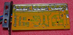
Shenzhen (ecrazyman) Controller Information

steveo said:
Hey Fechter

I will try placing a 1k resistor accross r7; I am currenting using a 10k + 5k resistor in series with my 100k pot; What resistance should i try in series with my 100k pot?

thanks
-steveo

The value of the fixed resistor in series with the pot will determine the upper limit. I'd try using just the 10k to start and see what you get. If it maxes out too low, then use a lower value.
 
I gave my unmodified 72v Knuckles controller a real beating during my vacation last week and it came out smelling like a rose. I'm running 72v with dual 36v15ah Ping packs in series with protection diodes. My thrashing included about 50 miles of riding on the beach at low tide with the wire end up high in my triangle using drip loops and tape to avoid water entry via the wires. I didn't protect the other end at all and it was stayed dry as a bone inside the controller, unlike the rest of my bike, so the rubber gaskets work well. Once I finalize any mods, I'll take more steps to thoroughly waterproof at the end covers, wires plug, and FET screws on the side.

At this point I'm totally happy, and will try to get it running my 2kw 2 speed Erato hub motor this week and report back. After a rewire job on my hub motor after an insufficient dropout mishap, I'm confident that I can figure out this Erato motor wiring now. The halls and wires seem fine, and I'll just have to assume the equally spaced hall sensors around the circumference must be either 60° or 120° phasing, which the controller can handle.

Keep up the great work!

John
 
hey.
fechter, the controller from your first post looks like the controller i have could come from the same company...

here are pics:


http://www.kraeuterbutter.at/Bilder2/Radnabenmotor_Vorderreifen/Regler/Regler_offen_DSCF2627.jpg
(the LED as you also described one)

http://www.kraeuterbutter.at/Bilder2/Radnabenmotor_Vorderreifen/Regler/Regler_offen_DSCF2625.jpg
the connectors are some i soldered there, so not original

http://www.kraeuterbutter.at/Bilder2/Radnabenmotor_Vorderreifen/Regler/Regler_Rueckseite_DSCF2631.jpg

here you can see: it has 5 pins with an jumper
(i guess for programming cut-off-voltage, and other things ?!?!?)

here how it looks closed:
http://www.kraeuterbutter.at/Bilder2/Radnabenmotor_Vorderreifen/Controller.jpg

http://www.kraeuterbutter.at/Bilder2/Radnabenmotor_Vorderreifen/Controller_Beschriftung.jpg

and thats how i thought the wiring has to be done..
http://www.kraeuterbutter.at/Bilder2/Radnabenmotor_Vorderreifen/Steckerbelegung_Steuereinheit_klein_Beschriftet.jpg


well: i can connect it, i hear the spark from the capacitor charing... but nothing happens..
should there be a beep or something ?

when i open the casing, the red LED is flashing, so at least: the LED has some electricity..

any ideas...
i would also like to know what the jumper is for, what options i have with it
 
Dang, they shrunk the controller.

I don't think it's from the same place, but does share many similarities.

My german is not so good, but it looks to me like perhaps you have the two 6 pin connectors reversed. The one to the right in the picture looks like the hall sensor connector. I have no idea what the other one would do.

It might be possible to trace the wires to the board to get a better idea of their function. There are so many wires on one end of the board it's hard to see the parts under them.
The hall sensor connector should have 5v between the red and black when the unit is powered on. The yellow, green and blue wires would also likely have 5v with no motor attached.

If the controller detects a hall sensor fault, it may be inhibiting operation and blinking a code with the LED. A fault in the throttle, brake, or low voltage will also trigger a fault code.

How many blinks do you get when you power it on?
 
Hi guys, I'm contacting ecrazyman for a cool project that will make this controller even more "the best" then it already is... :D Just stay tuned!
Anyway, I'm a professional developer with Microchip products, and I would like to suggest some interesting readings:

Brushless DC Motor Control Made Easy http://www.microchip.com/stellent/idcplg?IdcService=SS_GET_PAGE&nodeId=1824&appnote=en012037
Brushless DC (BLDC) Motor Fundamentals http://www.microchip.com/stellent/idcplg?IdcService=SS_GET_PAGE&nodeId=1824&appnote=en012127

The ecrazyman controller, as someone stated, is based on a PIC MCU, but not the ones you listed. Based on the hints given here it looks like the part is either PIC18F2331 or a PIC18F2431. The funny thing is that I was already planning to create my own controller, imagine the surprise when I opened up ecrazyman's one to find out that he implemented the same design that I had in mind!

Well, here's the AppNote on wich ecrazyman's controller is based: http://www.microchip.com/stellent/idcplg?IdcService=SS_GET_PAGE&nodeId=1824&appnote=en012145
I hope this helps everybody to better understand how this thing work and troubleshoot your problems!
:D
 
Hello...
first: thx ! so far

so:
i connected the controller without any wires connected to a battery
--> LED flashs.. äh... 32 times (i stopped counting)

then i noticed: when i use the switch (3 way: pedelec, off, and offroad (= throttlebar))
at one possition the LED turns off... (its not he switch-off-possition ?!?)

then i followed the wires:
the switch-possition were the LEDs goes down, is the one, where the wires yellow and red are shortened

so: i soldered the yellow wire coming from the swith to the yellow wire on the controller (the yellow on the swith is the one, which is always needed (for pedelec and for offroad when you know what i mean ?!?)

the red wire i soledered to the blue on the controller (there is no red on the controller)

well:
this blue wire ont he controller goes into the controller, but does not touch the platine, it is soldered to a red wire which runs OUT fo the controller to the throttlebar...

sofar: the switch-position were the LED goes off seems to be connected to the throttlebar

---------------
so: between red and black on the hall-sensor: 4.92Volt... so thats right

--------------
http://www.kraeuterbutter.at/Bilder2/Radnabenmotor_Vorderreifen/Steckerbelegung_Steuereinheit_klein_Beschriftet.jpg
left is the connector with 5 wires, so i thought that was the hall-sensor-cables (also the colors match this drawing: http://www.kraeuterbutter.at/Bilder2/Radnabenmotor_Vorderreifen/Schaltplan.gif )

right is a connector with 6 wires.. three going to the throttlebar, three to the switch (i readed the colors of the wires out of the plan.. unfortunatley the wires from throttlecontroller and swith do not match the controller-colors

maybe i have miss-wired the throttlebar ?!?
(But i thought the unit should also work without that in pedelec mode)
 
gip_mad said:
Hi guys, I'm contacting ecrazyman for a cool project that will make this controller even more "the best" then it already is... :D Just stay tuned!
Anyway, I'm a professional developer with Microchip products, and I would like to suggest some interesting readings:

Brushless DC Motor Control Made Easy http://www.microchip.com/stellent/idcplg?IdcService=SS_GET_PAGE&nodeId=1824&appnote=en012037
Brushless DC (BLDC) Motor Fundamentals http://www.microchip.com/stellent/idcplg?IdcService=SS_GET_PAGE&nodeId=1824&appnote=en012127

The ecrazyman controller, as someone stated, is based on a PIC MCU, but not the ones you listed. Based on the hints given here it looks like the part is either PIC18F2331 or a PIC18F2431. The funny thing is that I was already planning to create my own controller, imagine the surprise when I opened up ecrazyman's one to find out that he implemented the same design that I had in mind! :D

Nice to have software support. Keywin thinks the MCU is equivalent to a PIC16F72. It is marked HA3089, which does not show up on the Microchip web page. Maybe you can figure out what it is. If the chip really is a PIC18F series, then it should be able to clock up to 40mhz. The ecrazy controller does have connections for in-system programming. I also have what may be the code for it. It should be possible to get one and reprogram it with your own code. Now if you could find sensorless code that would work, that would be hot.
 
Kraeuterbutter said:
left is the connector with 5 wires, so i thought that was the hall-sensor-cables (also the colors match this drawing: http://www.kraeuterbutter.at/Bilder2/Radnabenmotor_Vorderreifen/Schaltplan.gif )

right is a connector with 6 wires.. three going to the throttlebar, three to the switch (i readed the colors of the wires out of the plan.. unfortunatley the wires from throttlecontroller and swith do not match the controller-colors

maybe i have miss-wired the throttlebar ?!?
(But i thought the unit should also work without that in pedelec mode)

Good you have a diagram, that helps.
I think this is a totally different controller, so it may be appropriate to move this discussion to a new thread.
I am not familiar with all those connections. Is there a pedelec sensor on the crank somewhere?
 
So you're telling me that Keywin doesn't have the source code? Mmmh... That complicates things. I'll contact him to get some more info.
it should be able to clock up to 40mhz
True, I can't explain why. But here is a list of pics specific for motor control:
http://www.microchip.com/ParamChartSearch/chart.aspx?branchID=55&mid=10&lang=en&pageId=74
and there are no 16F parts... It's, well, kinda "stupid" to reinvent the wheel writing code to manage all pwm lines by software... or does it use the only 1 pwm, controlling all mosfets via OR buffers like the crystalyte? This would make me really sad...
I'll study the PCB of the controller, but it's a pain, I just finished wiring it yesterday, and connected it to the bike with a lot of zip ties, making a very neat work... I'll have to rip it all apart to open the controller again. Less than 1km done with my first bike! :)
 
gip_mad said:
So you're telling me that Keywin doesn't have the source code? Mmmh... That complicates things. I'll contact him to get some more info.
it should be able to clock up to 40mhz
True, I can't explain why. But here is a list of pics specific for motor control:
http://www.microchip.com/ParamChartSearch/chart.aspx?branchID=55&mid=10&lang=en&pageId=74
and there are no 16F parts... It's, well, kinda "stupid" to reinvent the wheel writing code to manage all pwm lines by software... or does it use the only 1 pwm, controlling all mosfets via OR buffers like the crystalyte? This would make me really sad...
I'll study the PCB of the controller, but it's a pain, I just finished wiring it yesterday, and connected it to the bike with a lot of zip ties, making a very neat work... I'll have to rip it all apart to open the controller again. Less than 1km done with my first bike! :)
I have used the PIC 18F4331 (same as the 2331 etc) to control a brushless motor already, and it is a good micro with special hardware for hall effect based commutation. My hardware tests are photographed here (it is the triangular shaped one that I actually used for a number of tests with my ecycle brushless motor).
http://endless-sphere.com/forums/viewtopic.php?f=2&t=5157

This particular board I made over two years ago, and sadly didn't have the ecycle motor mounted on my ebike to do real (on road) tests as I could now. I remembered getting over 100Amps out of it during one test, with not much FET heating. One day though, I powered down the modules in the wrong order (had seperate supplies) and it went poof! At least my five paralelled shunt resistors melted and thus acted as fuses, avoiding event bigger damage. Ahhhh fond memories... :roll:
 
ZapPat,

This pcb may interest you. The MCU is called the INFINEON XC846 (27-mhz). All new code too (supposedly) and we are testing it now.
If all goes well it will run ANY PWM motor (PUMA included) at 72V nominal and probably beyond 50 amps ...

View attachment 2
DSC_0919a.JPG
This unit uses irfb4310 mosfets with the shunts set at 45 amps.
I should have it in my hands like tomorrow.

Welcome to ES btw. Cheers.
Knuckles

PS ... If you read Chinese you may enjoy this power point ... View attachment XC846.ppt
Heck ... Even if it was in English it would still be Chinese to me! I got the "Thank You" part at the end. "Toa Chie" :D
 
Thanks for the welcome, Knuckles! :mrgreen:

And yes your controller there looks very nice indeed, and it just so happens that I'm shopping for one ASAP to use with a golden motors 36V hub (and a 48V Ping2 on it's way too).

Does it do regen?

BTW, the general layout I find is clean and the design looks minimalist - usualy good. I'll have to read up on that micro it uses though, it's new to me.

I ideally would like a minimum 48V controller, that can hold at least 40A continous, brushless of course, with regen if possible. I will end up building my own ideal controller, but I want to get on the air right now!

Ciao!
 
Funny you should mention regen. OH ... What a topic! I don't have the strength to go into it right now but it is something I am passionate about and I have yet to read or see a truly good regen solution.

Are you an electrical engineer? I have so many ideas about regen but implementing it has yet to be really fruitful in the e bike realm.

Virtually all controllers regen. But do they regen while during a controlled and variable braking effort? (The Holy Grail of Regen). NO!

Asking if a controller "regens" is a loaded question. The question really is "How can I use my controller to brake my ride in a controlled fashion while simultaneously using that braking energy to charge my batteries?"

ANS: I have no clue! :cry:

http://endless-sphere.com/forums/viewtopic.php?f=2&t=5142&start=15#p82134
 
Very nice and clean circuit! But why did Keywin switch to Infineon? Why didn't he use a nice PIC, that works very well and it's highly hackable? :cry:
BTW, this is my request, I hope keywin will implement it on this new controller...:
Since the controller already have all necessary signals, and have already converted them in digital inside... Is it possible to make him send data parameters via the in-built serial port of the MCU? A simple pritocol, like:
[init byte 0x55][1 byte status][2 bytes voltage][2 bytes current][2 bytes hall speed]
so we (I) can make a simple "Cycle Analyst" connected with 2 wires. Every signal is already measured inside the MCU, so it's just a matter of putting it out via the serial port, wich requires about 2 instructions, and can be executed asynchronously in some spare time when the MCU is waiting for the next Hall sensor.
I hope it's clear... I offer to make the CA part, and to release it here for free, and keywin can start producing it if he wants, with his really nice PCBs.. Questions?
P.S.: sorry, but I have no Idea for the regen part! :roll:
 
gip_mad said:
But why did Keywin switch to Infineon?
The Infineon MCU (we believe) does not suffer from critical frequency limitations and is therefore a PUMA solution at 72V nominal and 45 amps! :shock:
Actually a PUMA motor at 72V and 45 amps will be CRAZY fast and powerful! But it can always be toned down.

[To 'gip_mad' ... I just sent you a PM about adding a MCU interface. ]
 
Yes, but the previous controller had problems because the MCU was not a specific MCU for that application. One of the 18F parts that I quoted is more then enough to drive almost ANY motor, the hall sensors are read using interrupts, after making the motor work I think you will still have about 60% of CPU power left to do your things... Plus they work at 40MHz! I don't like that Infineon part,it runs an 8051 and I consider it obsolete... Also, in big numbers they cost almost the same!
Well, anyway, if he choose the Infineon, he must have his reasons.
I know, I'm a Microchip fanboy! :mrgreen:
 
Knuckles said:
Funny you should mention regen. OH ... What a topic! I don't have the strength to go into it right now but it is something I am passionate about and I have yet to read or see a truly good regen solution.

Are you an electrical engineer? I have so many ideas about regen but implementing it has yet to be really fruitful in the e bike realm.

Virtually all controllers regen. But do they regen while during a controlled and variable braking effort? (The Holy Grail of Regen). NO!

Asking if a controller "regens" is a loaded question. The question really is "How can I use my controller to brake my ride in a controlled fashion while simultaneously using that braking energy to charge my batteries?"

ANS: I have no clue! :cry:

http://endless-sphere.com/forums/viewtopic.php?f=2&t=5142&start=15#p82134

I think maybe one problem may be that most current cheap controllers do not monitor and control the regen current themselves, maybe because of hardware limitations for one (thinkig negative shunt voltage here), and surely also because this type of feature is not found in most design references available (like microchip's). But I have yet to try one of these regen controllers myself, so I'm not too sure yet.
One thing for sure about regen, good efficiency is much harder to achieve because you are using a PWM boost circuit to recharge your batteries (the buck circuit becomes a boost during regen). This works OK with the motor running at higher speeds (higher EMF approaching battery voltage), but gets inefficient very quickly as the voltage produced by the motor drops far from what the battery's voltage is.
 
gip_mad said:
Yes, but the previous controller had problems because the MCU was not a specific MCU for that application. One of the 18F parts that I quoted is more then enough to drive almost ANY motor, the hall sensors are read using interrupts, after making the motor work I think you will still have about 60% of CPU power left to do your things... Plus they work at 40MHz! I don't like that Infineon part,it runs an 8051 and I consider it obsolete... Also, in big numbers they cost almost the same!
Well, anyway, if he choose the Infineon, he must have his reasons.
I know, I'm a Microchip fanboy! :mrgreen:

I hear ya, man!

I still haven't checked what this infinion part is all about, but why use generic MCU for motor control when we have a great one that does lots of what we want using hardware? Lots of example code available too, and so many people using PICs in general make for easy to find solutions to most any situation.
 
I have the code for the PIC version. I can't make any sense out of it, but that would be true of most any code.

Regen would be a nice feature if properly implemented.

It will not significantly increase your range or anything, but it really helps on long downhills.
Almost all the hardware needed to do it is already there, it would just be a matter of software and an input to the MCU to control it.

The regen current would need to be monitored also, and I'm not sure the shunt amplifier will work for regen. It may require a change in the shunt amplifier circuit to work both ways.

To get boost regen, you can switch all the low side FETs on at the same time, shorting the motor. The switch on time is short enough so the current never gets up too high. The switch is PWM'd so the current remains at or below the limit measured by the shunt.

By paying attention to the hall signals, there may be a more efficient way of switching the FETs.
 
Uhm... Based on that code, the PIC seems to be the popular 16F876.

Edit:
The code is incolplete, some of the interrupt part is missing... :cry:
 
fechter said:
I have the code for the PIC version. I can't make any sense out of it, but that would be true of most any code.

Regen would be a nice feature if properly implemented.

It will not significantly increase your range or anything, but it really helps on long downhills.

The guys testing two different controllers on the french forum report about 20-25% energy recuperated. This is testing done on one big hill, first going up, then going back down using regen, and manually regulating the regen to keep their speed around 30kph to have better efficiency.
For someone living in a hilly area this would be quite significant for them, and would also help out people who start and stop very often (like crowded city driving - shudder).

Almost all the hardware needed to do it is already there, it would just be a matter of software and an input to the MCU to control it.

The regen current would need to be monitored also, and I'm not sure the shunt amplifier will work for regen. It may require a change in the shunt amplifier circuit to work both ways.
This agrees with my earlier post about this problem. I guess we would have to study the circuit a bit to see if it would not too complicated fix this limitation.
To get boost regen, you can switch all the low side FETs on at the same time, shorting the motor. The switch on time is short enough so the current never gets up too high. The switch is PWM'd so the current remains at or below the limit measured by the shunt.
By paying attention to the hall signals, there may be a more efficient way of switching the FETs.
I can't agree with this first part at all, fetcher, since by shorting the motor like you suggest, you will not be getting ANY regen at all, this could merely be usefull to slow down the motor by dumping the energy into the FETs in case of an emergency or something (could use the top or bottom FETs for this BTW). Regen is done merely by lowering your duty cycle to a point where energy starts flowing backwards from your motor into your battery pack. You are now taking a lower voltage from the motor, and steping it up to a high enough voltage to start recharging your pack. There are a number of factors which influence the efficiency of such a system, a number of them external to your controller. Like charge acceptance of the battery for one... Supercaps would help greatly with this problem, but when oh when will they pop into existance?
 
gip_mad said:
fechter said:
I have the code for the PIC version.

What code? The code in the ecrazyman controller? Send Send Send! :mrgreen:

Old (open source) 36V code is posted here along with schematic ... http://endless-sphere.com/forums/viewtopic.php?f=2&t=5160#p82680

gip_mad said:
But code is missing also from your document...
Also found on Chinese forum here ... http://www.pic16.com/tigao/tig9.doc
 
Back
Top